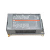
The ABB 07 DC 91 GJR5 2514 00 R0202, also recognized in engineering procurement databases as the 07DC91 GJR5251400R0202, is a dedicated decentralized digital input and output module designed for the Advant Controller 31 (AC31) automation system platform. Functioning as a remote station on the CS31 system bus, this module enables efficient distributed binary signal collection and field device actuation. The unit provides full electrical isolation between the EIA RS-485 communication line and the internal electronics, suppressing electromagnetic noise and safeguarding system logic integrity in harsh industrial environments. Diagnostic verification is simplified via an onboard array of 33 LEDs that provide local status indication for signal channels and bus fault execution.
Features
Integrates 16 dedicated binary inputs, 8 binary transistor outputs, and 8 software-configurable channels that operate dynamically as inputs or outputs.
Establishes robust distributed data links via the standardized EIA RS-485 CS31 system bus interface.
Ensures continuous system reliability through comprehensive electrical isolation between the CS31 bus interface and the remaining circuitry.
Features self-protecting transistor outputs equipped with automatic current limiting and thermal overload reactivation logic.
Incorporates an internal varistor to execute effective de-magnetization during inductive load switching phases.
Suppresses mechanical contact bounce via an optimized internal input hardware filter delay with a typical timing specification of 7 ms.
Streamlines network deployment with an onboard hardware coding switch located under a protective slide cover for explicit station address mapping.
Applications
Decentralized I/O expansion for Advant Controller 31 Hardware 90 Series architectures.
Distributed digital processing and binary status tracking in continuous manufacturing assembly blocks.
Localized field instrumentation and valve cluster control in industrial process environments.
Multi-channel safety monitoring and signal routing panels facing heavy electromagnetic interference.
Technical Data of the Complete Unit (07 DC 91)
Attribute
Value
Permissible temperature range during operation
0...55 °C
Rated supply voltage
24 V DC
Rated signal voltage for inputs and outputs
24 V DC
Max. current consumption without load
0.15 A
Max. rated load for supply terminals
4.0 A
Max. power dissipation in module (outputs without load)
5 W
Max. power dissipation in module (outputs under load)
10 W
Protection against reversed polarity of power connection
Terminals 24/25 (minus pole of supply voltage, terminal M)
Number of interfaces
1 CS31 system bus interface
Electrical isolation
CS31 system bus interface against the rest of the unit
Address setting
Coding switch under the slide cover located on the right side of the housing
Diagnosis
Operation and error messages: a total of 33 LEDs
Technical Data of the Digital Inputs
Attribute
Value
Number of channels per unit
16
Distribution of channels in groups
2 groups of 8 channels each, channels En.00...En.07, and En.08...En.15
Reference potential for all inputs
Terminals 24/25 (minus pole of supply voltage, terminal M)
Electrical isolation
from CS31 system bus
Input delay
typ. 7 ms
Signalization of input signals
one green LED per channel, LED activated according to the input signal
Input signal voltage:
- 0 signal
24 V DC
- 1 signal
-6 V...+5 V
- residual ripple at 0 signal
+13 V...+30 V
- residual ripple at 1 signal
within -6 V...+5 V
- residual ripple at 0 signal
within +13 V...+30 V
Due to the direct connection to the output, the demagnetizing varistor is also effective at the input when disconnecting inductive loads (see figure). This is why the difference between UPx and the input signal may not exceed the clamp voltage of the varistor. The varistor limits the voltage to approx. 36 V. Following this, the input voltage must range from -12 V to +30 V when UPx = 24 V and from -6 V to +30 V when UPx = 30 V. The following figure shows the circuit arrangement of a digital input/output.
The configurable channels are defined individually by the user program as either inputs or outputs. This is done by reading or writing data to/from the respective channel.
Attribute
Value
Number of channels per unit
8 inputs / transistor outputs
Distribution of channels in groups (when using channels as inputs)
1 group of 8 channels (channels En+1.00...En+1.07)
Distribution of channels in groups (when using channels as outputs)
channels An.08, An.15
Signalization of input and output signals
one yellow LED per channel, LED activated according to binary signal
according to DIN EN 50022-35, 15 mm deep. The DIN rail is centrally positioned between upper and lower edges of the module.
Mounting with screws
by 4 screws M4
Width x height x depth
120 x 140 x 85 mm
Connector
removable connectors with screw-type terminals
- conductor cross section
max. 2.5 mm² (grid space 5.08 mm)
- conductor cross section
max. 1.5 mm² (grid space 3.81 mm)
Weight
450 g
Dimensions for installation
refer to figure on next page
Installation Instructions
Attribute
Value
Installation position
vertical with connectors pointing up and down
Cooling
The natural convection cooling must not be hindered by cable ducts or other additional components installed in the cabinet.
Ordering Data
Attribute
Value
Module 07 DC 91
Scope of delivery
Order No. GJR5251 14 00 R0202
Digital Input/Output module 07 DC 91
24 V DC; 8 inputs / 8 transistor outputs
13-pin connector (grid space 5.08 mm)
9-pin connectors (grid space 3.81 mm)
Field Installation and Commissioning Notes
In most Advant Controller 31 systems, installation of the ABB 07 DC 91 (07DC91) is straightforward. However, commissioning issues are usually caused by incorrect address settings, communication wiring faults, or field wiring errors rather than module failure.
Before Applying Power
Before energizing the module, experienced field engineers typically verify three items first:
24 VDC supply polarity and voltage level
CS31 bus wiring continuity
Node address setting on the coding switch
Many communication faults reported during startup are eventually traced to duplicate CS31 addresses or reversed communication wiring.
Initial Power-Up Check
When power is applied, all LEDs should illuminate briefly while the module performs internal initialization.
If several LEDs fail to light during startup, check the power supply and connector seating before investigating network communication.
Once initialization is complete:
The communication LED should stop flashing.
Input LEDs should reflect actual field signals.
Output LEDs should respond to controller commands.
The red fault LED should remain OFF.
CS31 Communication Verification
A continuously flashing communication LED is one of the most common commissioning issues encountered in the field.
Before replacing the module, engineers should verify:
Correct node address assignment
CS31 bus polarity
RS-485 cable integrity
Controller configuration
Bus termination condition
In most cases, communication faults originate from network configuration rather than hardware failure.
Output Circuit Testing
During commissioning, outputs should be tested one channel at a time under actual load conditions.
If an output energizes briefly and then switches off, inspect the field device current draw. An overload or short circuit can activate the module's electronic protection circuit, causing automatic shutdown and restart attempts.
Repeated output cycling is often a wiring problem rather than a defective output channel.
Troubleshooting a Red Fault LED
If the red fault LED remains active, review recent field wiring changes before replacing the module.
Common causes include:
Short-circuited solenoid valves
Damaged field cables
Output overload conditions
Incorrect terminal wiring
CS31 communication faults
The diagnostic memory remains active until the fault has been corrected and acknowledged.
Module Replacement in Existing Systems
When replacing a failed 07 DC 91 (07DC91), always record the address switch setting before removing the original module.
After installation of the replacement unit:
Verify address switch settings.
Confirm 24 VDC supply voltage.
Check CS31 communication status.
Verify all field inputs.
Test critical outputs individually.
Review diagnostic status before returning the system to service.
Because channel allocation is controlled by the PLC application rather than stored in the module itself, additional configuration is generally not required after replacement.
Tip If a single output channel reports an overload alarm, do not immediately replace the module. The 07 DC 91 groups output diagnostics internally, meaning a fault on one field device can generate alarms affecting multiple output channels within the same protection group.
Technical Datasheet (PDF)Complete specifications and technical drawings.
Why does the red fault LED remain active after a short circuit has already been removed?
The 07 DC 91 stores diagnostic information until the fault is acknowledged. After correcting the short circuit or overload condition, the alarm can be cleared by holding the test button for approximately five seconds, through the PLC application program, or from an engineering workstation connected to the controller.
Why are output channels repeatedly switching OFF and ON during operation?
Repeated output cycling usually indicates an overload or short-circuit condition. The protection circuitry automatically disables the affected output and performs periodic restart attempts. If the fault remains present, the output continues cycling until the field wiring or connected load is corrected.
Why does the module report a fault on four outputs when only one channel is damaged?
Output diagnostics are monitored in protection groups. A short circuit on a single output can generate a fault indication for the entire output group. This behavior allows the controller to identify the affected protection section but may require additional troubleshooting to locate the exact failed channel.
Can the configurable I/O channels be used as both inputs and outputs at the same time?
Each configurable channel can operate either as an input or as an output according to the PLC application program. The operating mode is determined by how the channel is addressed within the control logic.
Why are configurable channels not responding correctly as digital inputs?
When a configurable channel is assigned as an input, the PLC application should not simultaneously force a logical output value to the same channel. Incorrect program allocation is one of the most common causes of unexpected channel behavior.
Does ABB 07 DC 91 (07DC91) store channel configuration internally?
No. Channel assignments are not stored within the module itself. The allocation of configurable channels is determined entirely by the application program running in the controller.
Can a failed 07 DC 91 (07DC91) be replaced without downloading a new PLC program?
In most installations, replacement does not require modification of the PLC application because the module does not contain user configuration data. Engineers should verify address switch settings, power connections, and CS31 network communication after replacement.
What should be checked if the CS31 communication LED continues flashing after startup?
A flashing communication LED typically indicates that the CS31 bus is not operating correctly. Engineers should verify node addressing, bus wiring polarity, controller configuration, cable continuity, and network termination conditions.
Can the module remain operational if one output channel experiences an overload?
Yes. The electronic protection circuitry isolates the affected output group while the module continues communicating with the controller. Diagnostic information is generated to assist fault localization.
Is external suppression required when driving inductive loads from the transistor outputs?
The module includes internal varistor protection for inductive load switching. However, engineers should evaluate field devices with high inductive energy and follow project-specific electrical design standards when additional suppression is recommended.
What is the most common cause of intermittent field I/O faults on a 07DC91 module?
Intermittent faults are commonly caused by loose terminal connections, unstable 24 VDC power supplies, damaged field wiring, excessive load current, or poor CS31 network connections. Field inspection and diagnostic review should be performed before replacing the module.
Can the 07 DC 91 (07DC91) be installed while the controller remains powered?
Hot replacement procedures depend on the specific Advant Controller 31 system design and plant operating practices. In most industrial environments, power isolation and lockout procedures should be followed before module installation or removal.
Global Express Shipping
Standard Delivery: 4-6 Business Days via DHL, FedEx, and UPS.
Express Dispatch: Same-day dispatch for in-stock orders placed before 2:00 PM (GMT+8).
Worldwide Coverage: Serving over 150 countries, including rapid delivery to Saudi Arabia and UAE.
Returns & Warranty
30-Day Guarantee: Returns accepted for in-stock products in original, factory-sealed packaging.
12-Month Warranty: Every industrial component is backed by our professional technical warranty.
Orders are processed and delivered Monday-Friday (excluding public holidays).
For full eligibility, restocking fees, and international return details, please view our official
Refund & Return Policy
.
Boolean logic is the foundation of every PLC program. From simple machine controls to complex industrial automation systems, logic gates determine how controllers respond to changing inputs and...
Industrial firewalls play a critical role in OT cybersecurity, protecting PLC, DCS, and SCADA networks through segmentation, ingress/egress control, and IDS/IPS integration aligned with IEC 62443...
Modern robotic grippers are evolving beyond traditional mechanical jaws. From gecko-inspired adhesive systems and soft food-grade grippers to AI-powered warehouse tools, advanced gripping...
From rope-driven DC compressors to battery-powered mine carts, early mining operations marked a turning point in industrial electrification. This article explores how electric motors transformed...
Factory I/O is transforming PLC education by delivering immersive 3D industrial simulations for students, engineers, and maintenance teams. The platform bridges the gap between theory and real-world...
This tutorial examines how onboard PLC functionality inside a CMZ SBD servo drive can execute standalone motion programs, including homing logic, position control, and cyclic axis movement without an...
Choosing a selection results in a full page refresh.