1 от 3

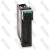
Allen-Bradley 1771-OB PLC-5 Digital DC Output Module

Allen-Bradley 1771-OB PLC-5 Digital DC Output Module

Only 8 item(s) left in stock
  • Manufacturer: Allen-Bradley

  • Product No.: 1771-OB

  • Country of origin:Съединени щати

  • Product Type: Digital Output Module

  • Barcode: 8537101190

  • Payment: T/T, Western Union

  • Weight: 900g

  • Dimensions: 3.5cm x 13cm x 14.5cm

  • Shipping port: Xiamen

  • Warranty: 12 months

Количество
Покажи пълните подробности

The 1771-OB is an 8-channel digital solid-state electronic device engineered for the PLC-5 / 1771 I/O Platform to drive low-voltage direct current industrial control hardware. It provides electrical switching paths for various field components, including DC motor drivers, status indicators, and industrial solenoid valves. The internal control micro-logic is energized via the local I/O chassis backplane rail, drawing a maximum current of 165 mA to maintain structural optoelectronic isolation between high-level plant field elements and core processor busses. System integration is established through the standard 1771-WA wiring arm connector assembly, permitting physical hot-swapping or card replacement sequences without disturbing landed field terminal connections.

Features

  • High-Density Output Distribution: Integrates eight independent solid-state DC switching circuits within a single-slot chassis package.
  • Dedicated Short-Circuit Protection: Individual 2 A, 8AG protective fuses mounted per channel safeguard the module against severe field overcurrent hazards.
  • Visual Status Array: Equipped with nine front-panel diagnostic LEDs providing localized visualization of blown-fuse status and specific channel conduction states.
  • Direct Input Interlocking: Supports zero-potential ground reference looping to directly drive discrete DC input modules, such as the 1771-IB receiver block.
  • Optoelectronic Backplane Protection: Incorporates continuous 1500 Vca (rms) galvanic isolation to prevent destructive external voltage transients from damaging backplane control logic.
  • Mechanical Slot Keying: Backplane socket keying fields restrict module slot alignment, ensuring only matched electrical module types sit within defined wiring nests.

Applications

  • Distributed control of factory floor solenoid-actuated pneumatic manifolds.
  • Direct activation of low-current DC motor speed control enable drives.
  • Remote instrumentation control panels and pilot lamp illumination matrix lines.
  • Inter-rack logic interlocking with low-voltage input hardware sub-assemblies.

Hardware Specifications

Parameter Specification
Manufacturer Allen-Bradley / Rockwell Automation
Model 1771-OB
Product Series PLC-5 / 1771 I/O
Module Type Digital DC Output Driver Module
Outputs Per Module 8
Chassis Compatibility 1771 I/O Chassis
Input Operational Voltage Range 10 Vdc to 27 Vdc
Output Current Capacity 1.5 A per individual output (not to exceed 8 A total per module)
Maximum Current Surge 4 A for 1 ms, repeatable at 1 s intervals
Off-State Leakage Current 1 mA maximum per output
On-State Voltage Drop 2 Vdc maximum
Signal Transmission Delay 10 ms (On to Off and Off to On states)
Power Dissipation 0.9 Watts minimum, 16.9 Watts maximum
Thermal Dissipation 3.0 BTU/h minimum, 57.6 BTU/h maximum
Backplane Logic Current Demand 165 mA @ 5 Vdc plus/minus 5%
Optoelectric Isolation 1500 Vca (rms)
Operating Temperature Range 0 degC to 60 degC
Storage Temperature Range -40 degC to 85 degC
Relative Ambient Humidity 5% to 95% (non-condensing)
Field Wiring Specifications Flexible cable with 1.5 mm2 nominal cross-section
Backplane Plastic Keying Slots Between positions 4 and 6, and between positions 18 and 20
Internal Fusing 2 A, 8AG rating (one individual fuse per output path)
Terminal Connection Block 1771-WA Wiring Arm

Connections/Interfaces

Connector Terminal Pin Function
Terminal A +DC Voltage Supply Input Reference
Terminal 0 Digital Output Channel 0 Signal Line
Terminal 1 Digital Output Channel 1 Signal Line
Terminal 2 Digital Output Channel 2 Signal Line
Terminal 3 Digital Output Channel 3 Signal Line
Terminal 4 Digital Output Channel 4 Signal Line
Terminal 5 Digital Output Channel 5 Signal Line
Terminal 6 Digital Output Channel 6 Signal Line
Terminal 7 Digital Output Channel 7 Signal Line
Terminal B DC Common Ground Return Reference

Engineering Notes

  • Terminal to Bit Discrepancy: The terminal channel designations etched on the physical 1771-WA wiring arm hardware do not directly map to software internal image register data bits. Refer strictly to the system allocation table when building control code.
  • Potential Equalization: When cross-linking an output channel directly into an input processing unit (such as a 1771-IB), a common power supply loop must feed both blocks to tie all reference grounds to an identical voltage potential.
  • Polarity Critical Warning: Correct structural polarity must be maintained on all direct current power terminals. Applying alternating current (AC) power configurations or cross-wiring polarity rails will result in critical module hardware destruction.
  • Backplane Power Balancing: The 165 mA backplane current consumption must be calculated into the aggregate power supply capacity budget of the specific 1771 chassis rack to avoid thermal overloading or backplane dip errors.

Field Guidelines

  • Electrostatic Grounding Procedures: Operators must latch an approved ESD wrist grounding strap to a structural physical ground point or discharge local potentials by touching an earth-grounded steel frame before touching card edges.
  • Plastic Keying Installation: Ensure the chassis backplane keying pegs are properly seated at the factory positions (between pins 4/6 and pins 18/20) to prevent the accidental insertion of mismatched voltage cards.
  • Chassis De-energization: Complete chassis rack power downcycles are required prior to sliding the driver module out of its physical slot to protect operators and prevent inductive backplane transients.
  • Fuse Extraction Protocol: To safely swap a compromised fuse assembly, release the front mechanical swing arm latch, withdraw the board housing, undo the two case retention screws, and replace the spent 2 A, 8AG component inside.

Technical & Procurement FAQ

Q: What specific fuse replacement specification must be used if a channel drops out? A: Each individual output switch is paired with a standard 2 A, 8AG form-factor fuse accessible underneath the card side cover.

Q: Can this DC driver module be safely slotted into the leftmost slot of a 1771 chassis? A: No, the far-left slot of the 1771 chassis configuration is structurally reserved for the master processor module or remote I/O network adapter head.

Q: Does the module display indicators on the front face for individual circuit diagnostics? A: Yes, it features one dedicated red LED for blown fuse notification alongside eight individual red status LEDs that light up when an output channel is actively energized.

Глобална експресна доставка

  • Стандартна доставка: 4-6 работни дни чрез DHL, FedEx и UPS.
  • Експресна изпращане: Изпращане в същия ден за налични поръчки, направени преди 14:00 ч. (GMT+8).
  • Глобално покритие: Обслужваме над 150 държави, включително бърза доставка до Саудитска Арабия и ОАЕ.

Връщания и гаранция

  • 30-дневна гаранция: Връщания се приемат за налични продукти в оригинална, фабрично запечатана опаковка.
  • 12-месечна гаранция: Всеки индустриален компонент е подкрепен с нашата професионална техническа гаранция.

Поръчките се обработват и доставят от понеделник до петък (с изключение на официалните празници).


За пълна информация относно допустимост, такси за презареждане и международни връщания, моля, разгледайте нашия официален Политика за възстановяване и връщане .

TECHNICAL SPECIFICATIONS

Color pattern
Черно
Country of origin
Съединени щати
Power source
Постоянен ток

Наскоро разгледани продукти

Технически знания

Electric Actuators Designed to Replace Fluid Power Systems: A Practical Industrial Automation Guide

This article explains how integrated electric actuators, such as SMC’s e-Actuator series, are transforming industrial motion control by replacing traditional pneumatic and hydraulic systems. It...

Math Operations Using OpenPLC for Industrial Automation Applications

This article explains how PLC systems perform core mathematical operations such as addition, subtraction, multiplication, division, modulo, and exponentiation within industrial automation. It shows...

Advanced Boolean Logic with FBD PLC Programming: Practical Industrial Applications Beyond Basic Logic

The article explains several advanced Boolean logic functions used in PLC programming beyond basic AND, OR, and NOT operations. It covers how tools like truth tables, multiplexers, pulse generators,...

Boolean Logic in PLC Programming: Understanding FBD Logic Gates

Boolean logic is the foundation of every PLC program. From simple machine controls to complex industrial automation systems, logic gates determine how controllers respond to changing inputs and...

Deep-Dive Guide to Industrial Firewalls and OT Network Segmentation

Industrial firewalls play a critical role in OT cybersecurity, protecting PLC, DCS, and SCADA networks through segmentation, ingress/egress control, and IDS/IPS integration aligned with IEC 62443...

Guide to Robotic Grippers: From Delicate Handling to Heavy-Duty Automation

Modern robotic grippers are evolving beyond traditional mechanical jaws. From gecko-inspired adhesive systems and soft food-grade grippers to AI-powered warehouse tools, advanced gripping...