Функционална интеграция и промишлено приложение
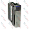
X20BR7300 (X20BR7300) функционира като високопроизводителен комуникационен модул на системно ниво и децентрализиран приемник на шината в екосистемата за автоматизация B&R X20. Проектиран да разширява локалните архитектури на задния панел в разпределени мрежи, този модул изпълнява двойна функция: действа като физически трансивър за високоскоростни CAN шинни мрежи и едновременно осигурява регулирано захранване за вътрешната логика и работата на X2X Link.
Този модул често се използва в сложни разпределени топологии, например в заводи за производство на пластмасови екструдирани изделия, многoетапни линии за опаковане на хартия и клетки за автомобилен монтаж, където I/O станциите са физически изолирани от основния контролер. Чрез автоматично изпълнение на обновяванията на фърмуера директно по пътя на upstream полевата шина устройството премахва необходимостта от ръчна поддръжка, осигурява единна софтуерна база за всички downstream възли и минимизира времето за възстановяване на системата при подмяна на компоненти през жизнения им цикъл.
Мрежова топология и инфраструктура за захранване
Архитектурата на този модул осигурява директно физическо терминиране към вътрешния заден панел B&R X20 и поддържа разширяване с до 43 последователно свързани дискретни или аналогови I/O модула. Работейки със скорост на предаване 1 Mbit/s по CAN интерфейса, той осигурява детерминирана синхронизация на данните, без да въвежда мрежови джитър или грешки от загуба на пакети.
Интегрираната подсистема за захранване приема номинално входно напрежение 24 VDC и го преобразува в изолирани захранващи линии, предназначени за захранване на логиката на вътрешния заден панел и задвижване на високоскоростната комуникационна шина X2X Link. Тази вътрешна изолация на шината предотвратява появата на заземителни контури и високочестотни смущения, които могат да нарушат сигналите за данни, като осигурява постоянна цялост на задния панел в среди със силни колебания на електромагнитното поле.
Матрица на техническите характеристики
| Параметър |
Подробности за спецификацията |
| Модел |
X20BR7300 |
| Марка |
B&R (Bernecker + Rainer) |
| Произход |
Австрия |
| Тип модул |
X20 приемник на шината / CAN I/O комуникационен модул |
| Захранващо напрежение на входа |
24 VDC (допуск от -15% / +20%) |
| Допустим товар на контакта |
10 A непрекъснато |
| Максимален капацитет за разширение |
Свързва до 43 I/O модула |
| Комуникационен интерфейс |
Интегрирана CAN шинна структура |
| Скорост на предаване по полевата шина |
Максимум 1 Mbit/s |
| Съвместимост на системата |
Всички стандартни задни панели от серията B&R X20 |
| Степен на защита на корпуса |
IP20 |
| Ориентация на монтаж |
Механично заключване на монтажната шина с щракване |
| Включени аксесоари |
Крайни капаци за X20 |
| Тегло |
0,28 kg (тегло при доставка: 2,0 kg с индустриална защита) |
| Работна температура |
От 0 до 55 °C (без кондензация) |
Инженерни запитвания и диагностични методи
-
Как се изпълнява функцията за автоматично обновяване на фърмуера по CAN шината?
Когато разширителна станция се инициализира, главният контролер сканира хардуерната конфигурация и сравнява вградения фърмуерен подпис на X20BR7300 с основния софтуерен образ. Ако бъде установено несъответствие, контролерът предава правилния двоичен пакет с фърмуер по полевата шина и презаписва локалната флаш памет, без да са необходими външни инструменти за програмиране или ръчни настройки на DIP превключватели.
-
Какви симптоми се появяват, ако ограничението за контактно натоварване от 10 A бъде превишено от страната на захранването?
Превишаването на максималния токов праг от 10 A през контактната структура на клемите ще предизвика вътрешно термично претоварване, водещо до спад на напрежението по вътрешните логически шини. Когато захранването на логиката спадне под допустимите граници, следващите модули губят синхронизацията на комуникацията, процесорът отчита грешка за прекъсване на X2X Link, а възелът преминава в безопасно състояние на изолиране без захранване.
-
Какви стъпки са необходими за осигуряване на правилно терминиране във физическия край на конфигурация от X20 модули?
X20BR7300 включва стандартни крайни капаци X20. Тези капаци не са декоративни; те завършват структурния и екраниращия път на вътрешната шина на задната платка. Ако крайният капак не бъде монтиран, вътрешните линии за данни остават изложени на околните електромагнитни смущения и се прекъсва структурната непрекъснатост, което може да причини непредвидими прекъсвания на данни или грешки при инициализацията в целия стек от 43 модула.
Протоколи за пускане в експлоатация на място и безопасност
Разпределение на захранването и изолиране на веригата upstream
Свържете входното захранване 24 VDC към модула чрез отделен, стабилизиран промишлен захранващ източник. Монтирайте бързодействащ автоматичен прекъсвач 10 A upstream на захранващите клеми на модула, за да предотвратите повреди на вътрешните писти на задната платка вследствие на свръхток. Уверете се, че обратният път 0 VDC е надеждно свързан към заземителната шина на централния контролен шкаф, за да ограничите проблемите с синфазния шум.
Стандарти за окабеляване и терминиране на полевата шина
Всички връзки към CAN шината трябва да използват екраниран кабел с усукана двойка и характеристичен импеданс 120 ома. Монтирайте металослоест резистор 120 ома между линиите CAN_H и CAN_L във физически началния и крайния възел на сегмента на полевата шина. Отстранете част от изолацията на кабелния екран и го закрепете здраво в предоставените нискоимпедансни заземителни скоби на монтажната основа, за да отвеждате паразитния високочестотен шум далеч от комуникационните трансивъри.
Поставяне на модула и подравняване при плъзгане
Преди да поставите модула в основата му за включване, изключете всички основни и спомагателни захранвания. Подравнете направляващите релси на модула с гнездото на основата и плъзнете устройството вертикално надолу, докато механичните фиксиращи езичета се задействат с отчетливо щракване. Закрепете модула с вградените задържащи винтове, за да осигурите правилно заземяване към DIN шината; работата на задната платка без напълно затегнати винтове може да причини прекъсващи захранващи връзки при силни вибрации.