Описание
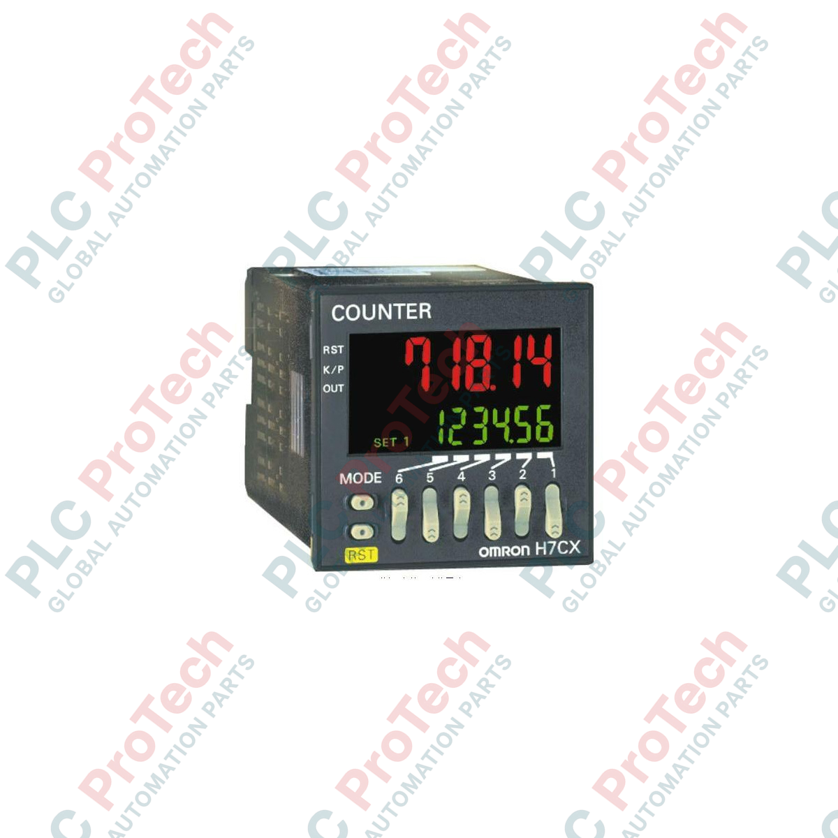
Безпроблемно интегриран в съвременни производствени линии, Omron H7CX-A11D1-N функционира като високоточен цифров брояч и тахометър по стандарт 1/16 DIN, проектиран за бързо наблюдение на импулси и координиране на изходите. Оборудван с ярък двуцветен PV дисплей, този многорежимен контролер позволява на операторите да проследяват броячи, партиди и показатели за скоростта върху един компактен панел. Устройството поддържа многоволтова управляваща шина и интегрира гъвкави контактни и полупроводникови изходни вериги за безопасно и надеждно управление на вторични процеси по автоматизация.
Основни характеристики
-
6-цифрен PV дисплей: Висококонтрастни символи в червено или зелено с възможност за конфигуриране за наблюдение на процесите в реално време.
-
Гъвкава многорежимна работа: Може да се конфигурира като едностепенен брояч, брояч на партиди, тотализиращ брояч, двоен брояч или цифров тахометър.
-
11-пинов цокълен интерфейс: Позволява бързо електрическо свързване, физическа подмяна и надеждна интеграция.
-
Хибридни конфигурации на изходите: Осигурява едновременно физически контактен изход (SPDT) и полупроводникови транзисторни изходи (NPN/PNP).
-
Универсално захранване с ниско напрежение: Съвместимо с електроразпределителни мрежи както с 12 до 24 VDC, така и с 24 VAC.
Индустриални приложения
- Високоскоростно броене на опаковки, сортиране и обемно броене на кашони.
- Мониторинг на скоростта на въртящи се машини и тахометрично измерване на скоростта на непрекъснати линии.
- Системи за броене на циклите при пакетни процеси и управление на рязането на материали.
- Позициониране и измерване на размери чрез входове за квадратурни импулси.
Технически спецификации
| Параметър на спецификацията |
Инженерна стойност |
| Производител |
Omron |
| Обозначение на модела |
H7CX-A11D1-N |
| Цифри на дисплея |
6 цифри (от −99999 до 999999) |
| Захранващо напрежение |
12 до 24 VDC / 24 VAC при 50/60 Hz |
| Външни връзки |
Схема на свързване към 11-пинова цокълна основа |
| Скорост на обработка на входния сигнал |
30 Hz или 5 kHz (избира се чрез DIP превключвател) |
| Типове изходи |
Контактен изход (SPDT: 250 VAC, 3 A резистивен) и транзисторен изход (NPN/PNP с отворен колектор: 30 VDC, 100 mA) |
| Диапазон на защита на клавишите |
Физическо блокиране чрез вътрешни нива на фърмуера |
| Работен температурен диапазон |
от −10 до 55 °C (без обледеняване или кондензация) |
| Степен на защита на лицевия панел |
IP66 / NEMA 4X (защитен от прах и капки) |
| Тегло при доставка (изчислено) |
2,0 kg (включително слоевете на защитната опаковка) |
| Размери на лицевия панел (изчислени) |
48,0 mm x 48,0 mm (монтаж на панел по стандарт 1/16 DIN) |
| Дълбочина на вграждане на корпуса |
84,1 mm |
Свързване и интерфейси
| 11-пинова клема |
Задаване на функцията |
| Пин 1 |
Общ вход (GND) |
| Пин 2 |
Захранващ вход (12–24 VDC / 24 VAC) |
| Пин 3 |
Вход за броене 1 (входен сигнал CP1) |
| Пин 4 |
Вход за броене 2 (входен сигнал CP2) |
| Пин 5 |
Вход за нулиране / команден сигнал от шлюза |
| Пин 6 |
Емитер / общ извод на транзистора |
| Пин 7 |
Захранващ вход (12–24 VDC / 24 VAC) |
| Извод 8 |
Колектор на транзисторния изход (опция NPN/PNP) |
| Извод 9 |
Общ контакт на изходното реле (COM) |
| Извод 10 |
Релеен контакт на изхода, нормално затворен (NC) |
| Извод 11 |
Релеен контакт на изхода, нормално отворен (NO) |
Емпирични инженерни изводи
Алтернативни модели и съвместимост
Вариантите със суфикс -N директно заменят остарелите 11-пинови модели H7CX. Въпреки че разпределението на изводите остава напълно идентично, имайте предвид, че стандартните и по-новите ревизии може да имат различни вътрешни програмни параметри по подразбиране. Проверете конфигурацията на DIP превключвателите отстрани на корпуса, за да се уверите, че вътрешните коефициенти на деление, режимите на броене и профилите на реакция съответстват на конфигурацията на съществуващата инсталация.
Практически проблеми при приложенията и инженерни бележки
При конфигуриране за максимална честота на броене 5 kHz се уверете, че входните сигнали идват от полупроводникови безконтактни сензори за близост или ротационни енкодери. Механичните контактни входове ще бъдат засегнати от отскачане на контактите, което води до нестабилно и погрешно отчитане на високи нива. Ако трябва да се използва интерфейс с механичен превключвател, намалете максималната входна честота на броене до 30 Hz чрез физическите DIP превключватели, за да активирате вътрешния нискочестотен филтър за шум.
Съвети за въвеждане в експлоатация и окабеляване
Уверете се, че всички високоволтови кабели (особено изходните контакти, които превключват големи индуктивни товари) са прокарани физически отделно от линиите на входните сензори. Използвайте екранирани кабели с усукани двойки за входовете CP1, CP2 и Reset, като заземите екрана единствено на клемния блок на панела, за да ограничите електромагнитно индуцирания шум в сигнала от намиращите се наблизо активни задвижвания и комутационна апаратура.
Указания за монтаж
КРИТИЧНО ПРЕДУПРЕЖДЕНИЕ: Преди да предприемете физически монтаж, окабеляване или процедури по поддръжка, уверете се, че всички основни, спомагателни и захранващи линии, подаващи напрежение към панела, са напълно обезточени. Проверете дали във вторичните кондензаторни блокове или сензорните линии няма остатъчен заряд, за да избегнете повреда на оборудването или опасност от токов удар.
1
Подгответе стандартен изрязан отвор в панела с размери 45,0 mm x 45,0 mm, съответстващ на стандартните спецификации на DIN.
2
Поставете водоустойчивото уплътнение около предния издаден ръб на корпуса, за да осигурите защита на предната страна по NEMA 4X / IP66.
3
Плъзнете модула отпред в изрязания отвор на панела, след което плъзнете монтажната адаптерна скоба върху корпуса отзад и затегнете физическите винтове на панела само до плътно прилепване.
4
Конфигурирайте физическия блок DIP превключватели, разположен на задния или страничния панел, според необходимата функция, логиката на входа (NPN или PNP) и изискванията за скорост на сензора.
5
Проверете контурите на свързване спрямо картата на конфигурацията на изводите на 11-пиновия цокъл, закрепете цокъла към устройството и подайте захранващите линии, за да започнете въвеждането в експлоатация.