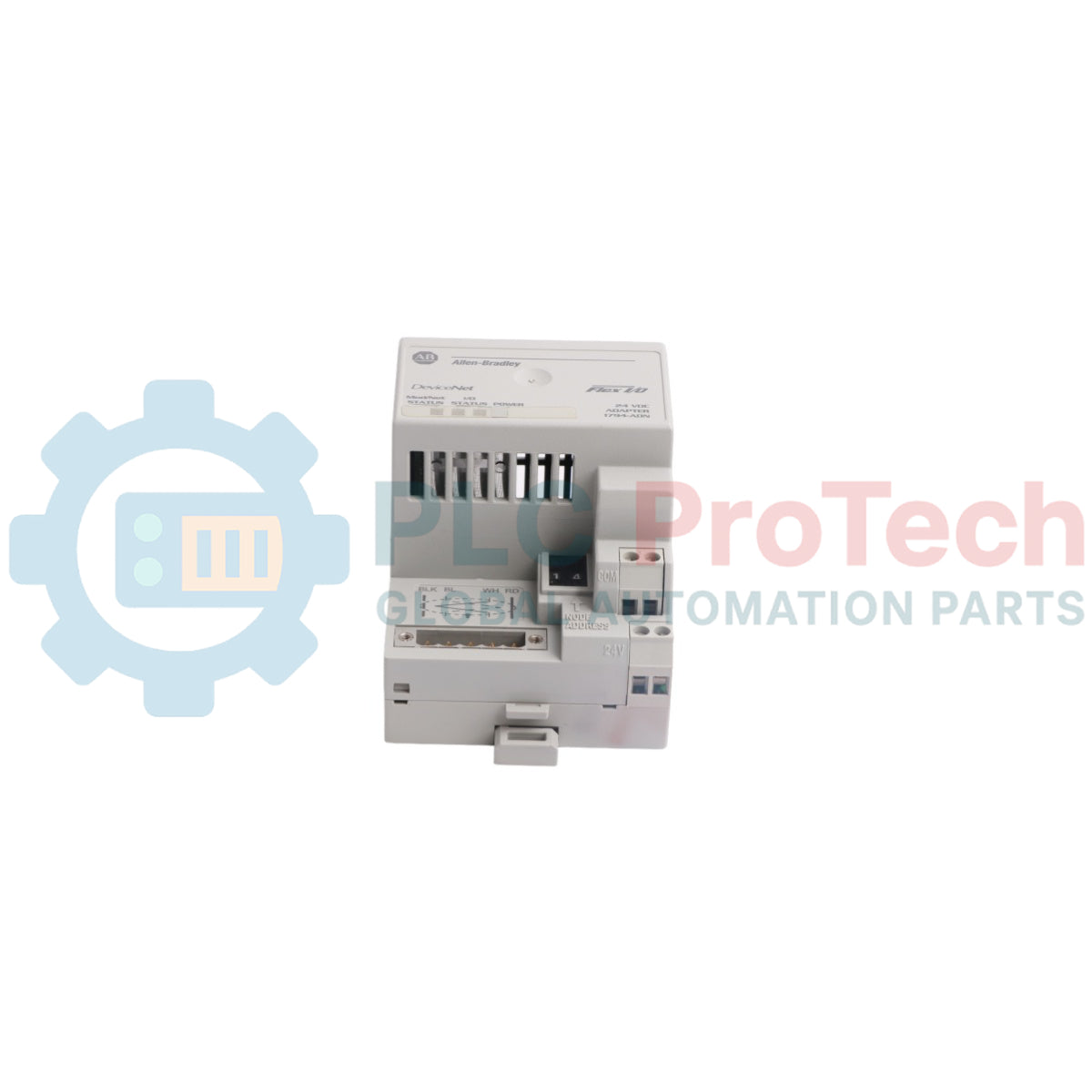
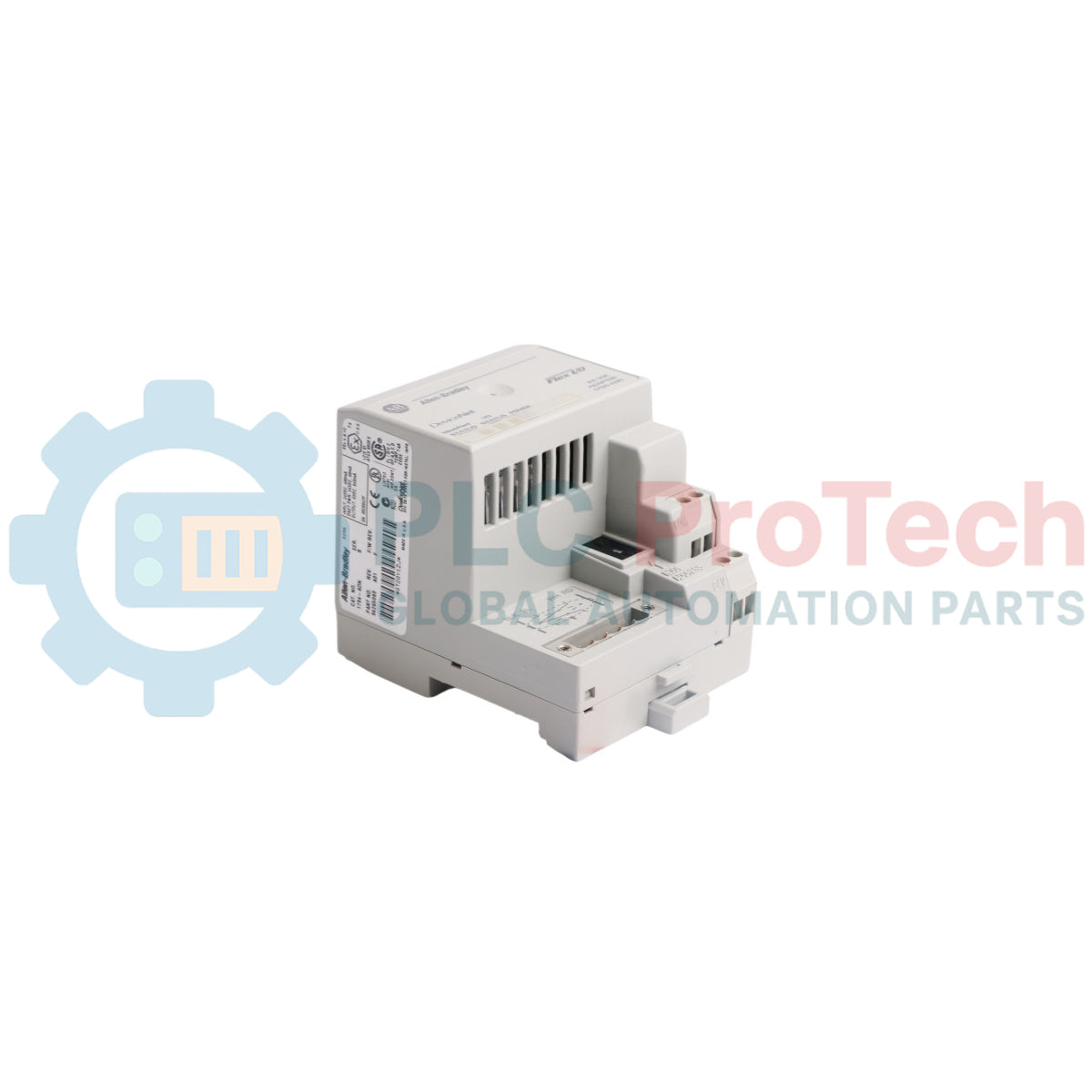
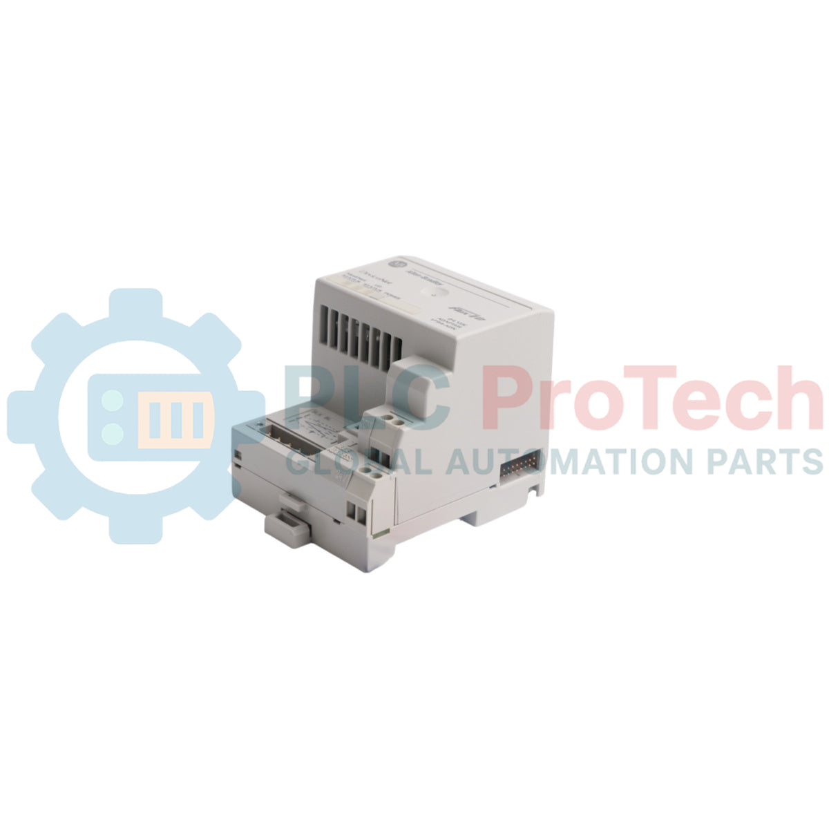
The 1794-ADN is a network communications adapter designed for the FLEX I/O distributed input/output platform. This component serves as the physical and logical gateway linking a local cluster of up to eight digital, analog, or specialty operational modules to a centralized programmable logic controller over a DeviceNet network infrastructure. It manages high-speed, bidirectional data transactions, translating the subsystem bus variables across the proprietary FlexBus backplane into discrete application-layer frames specified by the open industrial network standard.
Operating as a standard slave device on the master bus, the module contains built-in microcontrollers that manage independent startup mapping routines, including a fresh out-of-the-box discovery protocol that auto-detects and allocates precise block dimensions per physical I/O slot. The integrated communication hardware accommodates a singular drop or daisy-chain linear topology using screw-secured plug-in connectors. The 1794-ADN is deployed inside industrial machine panels, remote sensor arrays, assembly plant conveyor lines, and localized processing skids requiring reliable, space-saving signal multiplexing to reduce physical panel wiring overhead.
Features
Interfaces a centralized DeviceNet infrastructure with local modular distributed FLEX I/O rails.
Automatic physical I/O slot discovery and configuration parsing during power-up sequence routines.
Removable front-mounted network screw connector to maintain cable bus connections during replacement cycles.
Direct internal translation capabilities for up to eight distinct operational backplane modules.
Three distinct diagnostic light-emitting diodes providing localized status logs for power, adapter, and network link states.
Applications
Distributed control panel sensor aggregation over wide production plant networks.
Automotive assembly station line monitoring and discrete block control.
Conveyor sortation systems and high-density packaging line distribution clusters.
Specialized manufacturing skid machinery data acquisition.
Technical Specifications
Parameter
Specification
Manufacturer
Rockwell Automation / Allen-Bradley
Brand
FLEX I/O
Part Number
1794-ADN
Module Type
DeviceNet Communications Adapter
I/O Module Capacity
8 Modules Maximum
Supported Protocols
DeviceNet
Network Baud Rates
125 kbps, 250 kbps, 500 kbps
Input Supply Voltage
24V DC Nominal
Operational Voltage Window
19.2V DC to 31.2V DC (Includes 5% AC Ripple)
Supply Current Draw
300 mA at 24V DC, 400 mA at 19.2V DC Maximum
DeviceNet Network Power Load
24V DC at 90 mA Maximum
FlexBus Power Delivery
640 mA at 5V DC Maximum
Isolation Voltage
50V Continuous (Basic Insulation Type)
Power Dissipation
7.6 W Maximum at 19.2V DC
Thermal Dissipation
26 BTU/hour Maximum at 19.2V DC
Enclosure Type Rating
Open Style / IP20
Wire Size Limits
22 AWG to 12 AWG Stranded Copper Rated at 75 Celsius Minimum
Operating Temperature
0 to 55 degC
Storage Temperature
-40 to 85 degC
Relative Humidity Window
5% to 95% Non-Condensing
Country of Origin
USA
Weight
195.5 g
Dimensions
87 mm x 68 mm x 69 mm
Connections/Interfaces
Connector Pin
Function
Terminal A
External Operational Supply +V DC Input
Terminal B
External Operational Supply -V Common Input
Terminal C
Chassis Functional Earth Ground Lead Connection
DeviceNet Pin 1 (Black)
Network V- Power Supply Reference Common
DeviceNet Pin 2 (Blue)
CAN_L Signal Communication Inverted Node
DeviceNet Pin 3 (Bare)
Network Cable Metallic Drain Shield Ground Node
DeviceNet Pin 4 (White)
CAN_H Signal Communication Non-Inverted Node
DeviceNet Pin 5 (Red)
Network V+ External Operating Power Rail
Installation Guidelines
DIN Rail Mounting
Tilt the top lip of the adapter bracket assembly onto an IEC-compliant 35 mm metallic DIN rail. Pivot the lower half of the module box downward until the spring-activated bottom tracking latch engages into a locked alignment. Install rigid physical end anchors flanking the boundary ends of the rail string to block lateral movement.
FlexBus Backplane Alignment
Position the network adapter module at the leftmost boundary slot of the mounting rail. Align the receiving notch profile on the lower right casing wall with the anchor hook on the first functional I/O terminal base, sliding the units firmly together until the side FlexBus connection bus path pins bridge fully inside the terminal sockets.
Wiring and Torque Requirements
Exclusively terminate field cables using stranded copper conductors inside specified gauge restrictions. Torque all front removable terminal block power connections to exactly 0.8 N-m (7 lb-in). Ensure power supply connection leads tracking the external direct current input are brief and do not exceed 3 meters in total length.
Noise Separation Regulations
Isolate network interface drop lines and associated FlexBus signaling rails away from electrical power drops, variable frequency drive output conduits, high-voltage switching fields, and heavy motor feeds to prevent high-frequency electromagnetic field induction.
FAQ
What is the maximum number of modules this adapter can drive?
The unit can interface with up to eight independent FLEX I/O modular blocks attached continuously to the right side of its backplane.
How is the unique network address defined on this specific component?
The node address is selected manually by adjusting the three mechanical rotary thumbwheel switches on the front facing panel before starting the network.
What power output does the internal circuit feed down the local backplane?
The adapter supplies a maximum current of 640 mA at 5V DC to power the logic chips of connected extension modules.
Does this device require power from both the external source and the network cable?
Yes, the internal backplane requires a standard 24V DC auxiliary source, while the primary transceiver circuit must receive power directly from the active DeviceNet trunk lines.
What do flashing red cycles on the Module/Network LED signify?
A flashing red indication represents a minor recoverable fault state, suggesting an address configuration conflict or a data register mismatch.
What is the maximum data rate supported across this link?
The adapter communicates at standard industrial intervals of 125 kbps, 250 kbps, and 500 kbps depending on total network loop lengths.
Can an engineer hot-swap the network adapter when the system is active?
No, while individual I/O modules allow removal under power, extracting the network adapter completely interrupts communication blocks for all eight secondary points.
What isolation rating is certified for this specific interface structure?
The unit features basic insulation certified for a continuous potential barrier up to 50V between user power lines and the system logic circuitry.
What setting initiates an absolute factory configuration wipe on the hardware?
Setting the three mechanical rotary switch dials to a code pattern of 888 and cycling power executes an internal memory clear routine.
What type of cabling is approved to bridge the primary bus connections?
The network link requires certified Belden YR-29832 or equivalent shielded industrial twisted-pair DeviceNet media.
A practical guide to replacing aging Bailey Symphony operator stations running on OpenVMS Alpha. It compares Alpha emulation, OpenVMS x86 migration, OPC re-platforming, and phased ABB modernization.
Maintenance data connects work orders, sensor signals, asset history, costs, and technician knowledge. Used well, it improves planning, reliability, predictive maintenance, spare-parts control, and...
Tento článek vysvětluje, jak integrované elektrické pohony, jako je řada e-Actuator od SMC, mění průmyslové řízení pohybu nahrazením tradičních pneumatických a hydraulických systémů. Zdůrazňuje...
Tento článek vysvětluje, jak PLC systémy provádějí základní matematické operace, jako jsou sčítání, odčítání, násobení, dělení, modulo a umocňování v rámci průmyslové automatizace. Ukazuje, jak tyto...
Článek vysvětluje několik pokročilých funkcí Booleovy logiky používaných v programování PLC nad rámec základních operací AND, OR a NOT. Popisuje, jak se v diagramu funkčních bloků (FBD) využívají...
Booleovská logika je základem každého programu PLC. Od jednoduchých ovládání strojů až po složité průmyslové automatizační systémy určují logické hradla, jak řadiče reagují na měnící se vstupy a...