Description
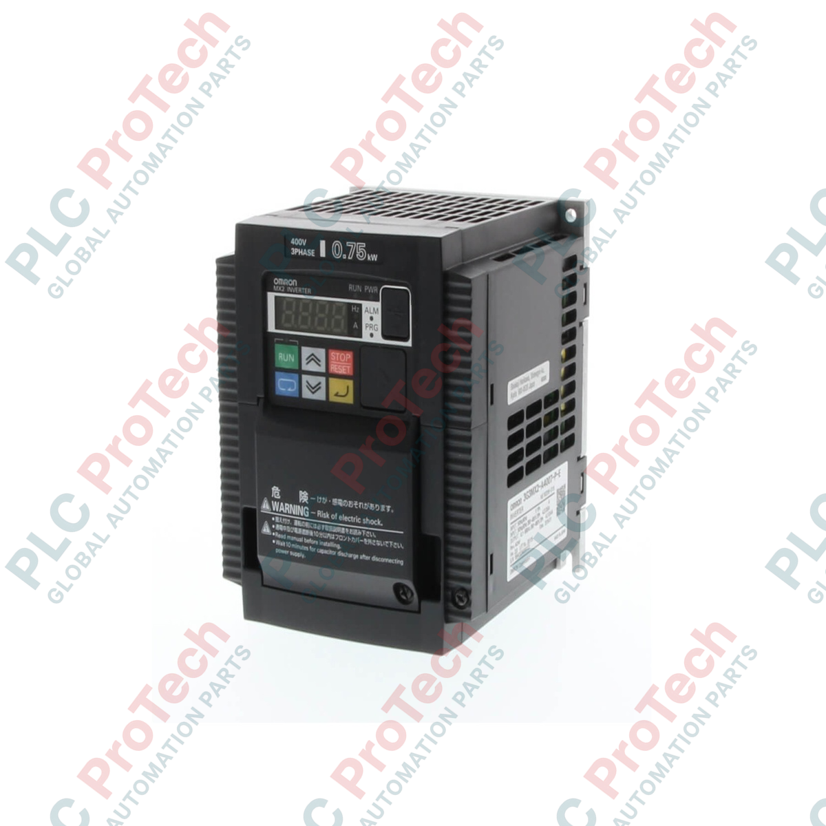
Engineered for highly dynamic industrial applications requiring precise torque and speed regulation, the Omron 3G3MX2-A4075-ZV1 variable frequency drive provides reliable 3-phase, 400 VAC power control for motors up to 7.5 kW in heavy-duty environments. This premium multi-function compact controller features advanced sensorless vector control capabilities, enabling 200% starting torque at speeds down to 0.5 Hz. With integrated dual ratings for Constant Torque (CT) and Variable Torque (VT) configurations, it adapts seamlessly to variable-load machinery while maintaining an exceptionally compact footprint. The ZV1 designation indicates enhanced firmware supporting advanced functionalities, making this unit a reliable component for modern machine design and complex automation architectures.
Features
-
Dual-Rated Flexibility: Readily configured for Constant Torque (7.5 kW) or Variable Torque (11 kW) loads to optimize inverter frame sizing.
-
High Starting Torque: Achieves 200% torque output at 0.5 Hz, making it suitable for high-inertia starting loads such as cranes and heavy conveyors.
-
Safety Integrated: Features dual-channel Safe Torque Off (STO) certified to ISO 13849-1 Cat 3 PLd and SIL2, reducing external safety relay requirements.
-
Positioning Functionality: Supports simple positioning profile execution directly within the drive without an external motion controller.
-
Modbus Connectivity: Standard Modbus RTU communications interface via RS-485, with optional communication cassettes for EtherCAT, DeviceNet, and PROFIBUS.
Applications
- High-speed manufacturing conveyor systems requiring rapid deceleration and positioning.
- Pumping, HVAC, and industrial fan systems utilizing energy-saving PID control loops.
- Winding, unwinding, and tension-controlled material handling equipment.
- Packaging, indexing, and food processing machinery requiring compact DIN-rail installation.
Technical Specifications
| Parameter |
Specification Value |
| Manufacturer |
Omron |
| Model Code |
3G3MX2-A4075-ZV1 |
| Input Voltage Class |
3-Phase 380 to 480 VAC (+10% / -15%), 50/60 Hz (+/-5%) |
| Max Motor Capacity (Constant Torque) |
7.5 kW (Heavy Duty) |
| Max Motor Capacity (Variable Torque) |
11 kW (Normal Duty) |
| Rated Output Current (CT) |
18.0 A |
| Rated Output Current (VT) |
23.0 A |
| Enclosure Protection Rating |
IP20 (Panel-mounting/closed wall-mounting) |
| Control Method |
Sine wave PWM (V/f control, Sensorless Vector control) |
| Operating Ambient Temperature |
-10 to 50 degC (no freezing or condensation) |
| Net Weight |
3.5 kg |
| Shipping Weight (Calculated) |
6.0 kg |
Connections and Interfaces
| Terminal Block |
Function Assignment |
| R/L1, S/L2, T/L3 |
Main Power Supply Input (3-phase AC) |
| U/T1, V/T2, W/T3 |
Inverter Output Terminals to Motor |
| PD/+1, P/+ |
DC Reactor connection terminals (remove short-circuit bar to install) |
| P/+, RB |
External Dynamic Braking Resistor connection |
| S1, S2, SC |
Dual-Channel Safety Inputs (STO) and Safety Common |
| 1 to 7 |
Multi-function Digital Inputs (Sink/Source selectable) |
| AM, AM-F, FS, FV, FI |
Analog Inputs (0-10V, 4-20mA) and Analog Monitor output |
Empirical Engineering Insights
Alternative Models & Compatibility
The -ZV1 suffix indicates the presence of advanced multi-function firmware that supports precise positioning control and specialized internal logical function blocks. It acts as a direct mechanical and electrical drop-in replacement for the standard legacy MX2-A4075 series, but configuration parameters related to internal PLC functions and positioning must be verified as older models lacked these registers.
Application Pitfalls & Engineering Notes
When installing the MX2 drive inside sealed MCC enclosures, heat dissipation is critical. At its maximum 7.5 kW output rating, the drive generates up to 300W of heat. Standard side-by-side mounting requires a minimum derating of 10% on continuous output current unless forced cabinet ventilation is utilized. For applications experiencing high regenerative energy (such as vertical hoisting or rapid deceleration profiles), the integrated braking transistor requires the addition of an external dynamic braking resistor connected to terminals P/+ and RB.
Commissioning & Wiring Tips
To avoid high-frequency electromagnetic interference (EMI) tripping the safety input loops or modulating the feedback signals, ensure that all control cables (especially analog and STO inputs) are routed in separate metal conduits away from the motor power leads. Shielded motor cable with symmetric ground conductors must be used, and the shield must be securely grounded directly to the chassis grounding plate of the drive.
Installation Guidelines
CRITICAL SAFETY WARNING: High voltage is present on power terminals and internal DC bus capacitors even after AC input power has been isolated. Before executing any maintenance or physical installation procedures, shut off main supply switches and wait a minimum of 10 minutes. Use a reliable digital multimeter to measure and verify that the voltage between terminals P/+ and N/- is under 45 VDC.
1
Ensure the mounting surface is vertically aligned and free from vibration. Secure the inverter frame using M5 bolts through the integrated heat sink mounting tabs.
2
Connect the protective earth (PE) ground lead directly to the main system ground busbar before connecting any input or output power cabling.
3
Terminate the AC power supply lines (R/L1, S/L2, T/L3) and the motor phases (U/T1, V/T2, W/T3) ensuring the correct torque specification is applied to the screw terminals.
4
For initial start-up, complete motor parameter auto-tuning via the built-in digital operator before commanding any physical load movements.