Description
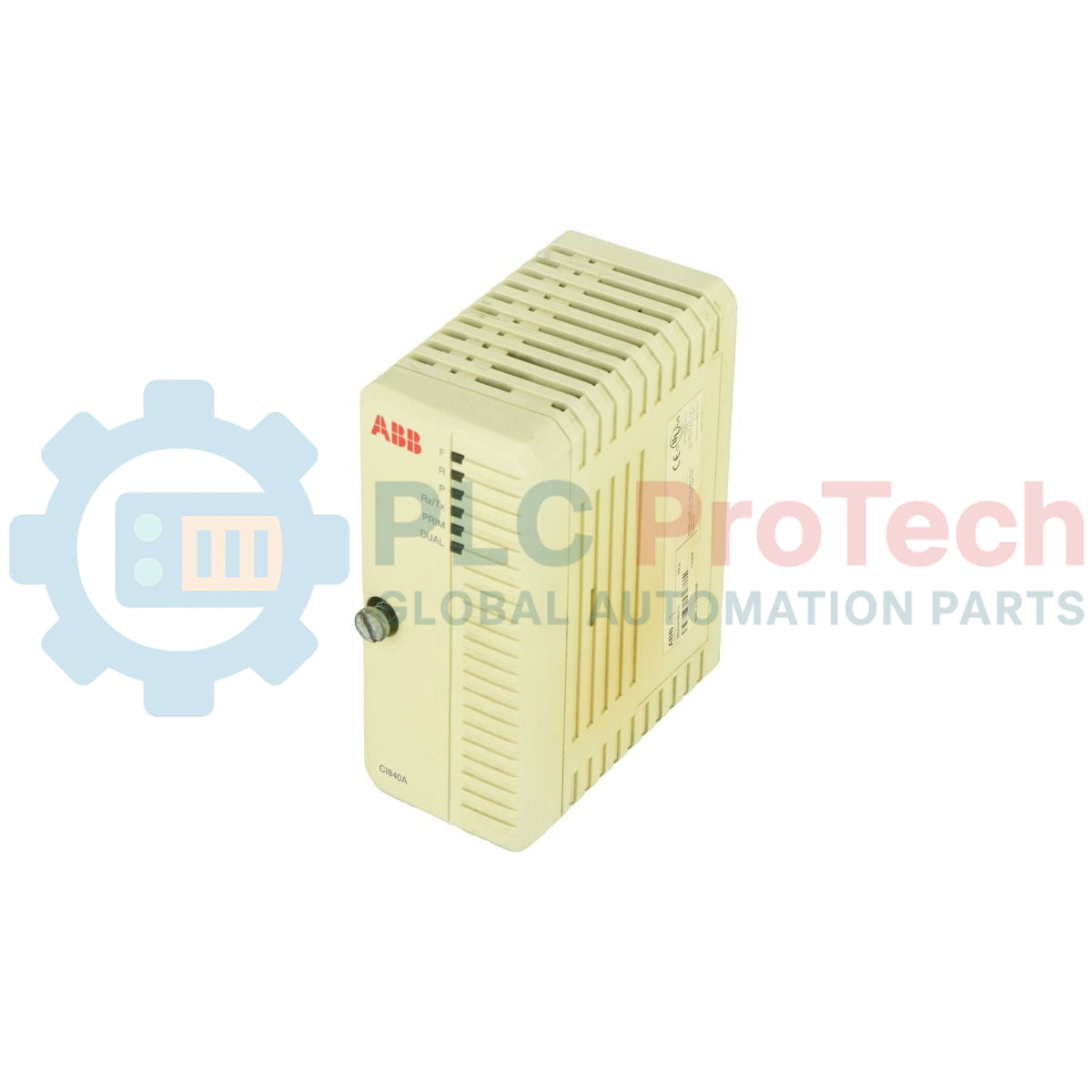
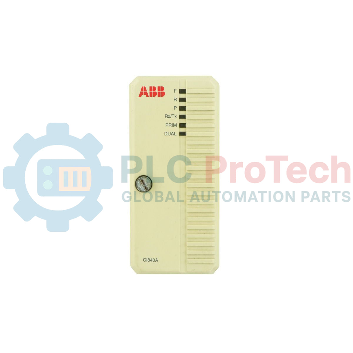
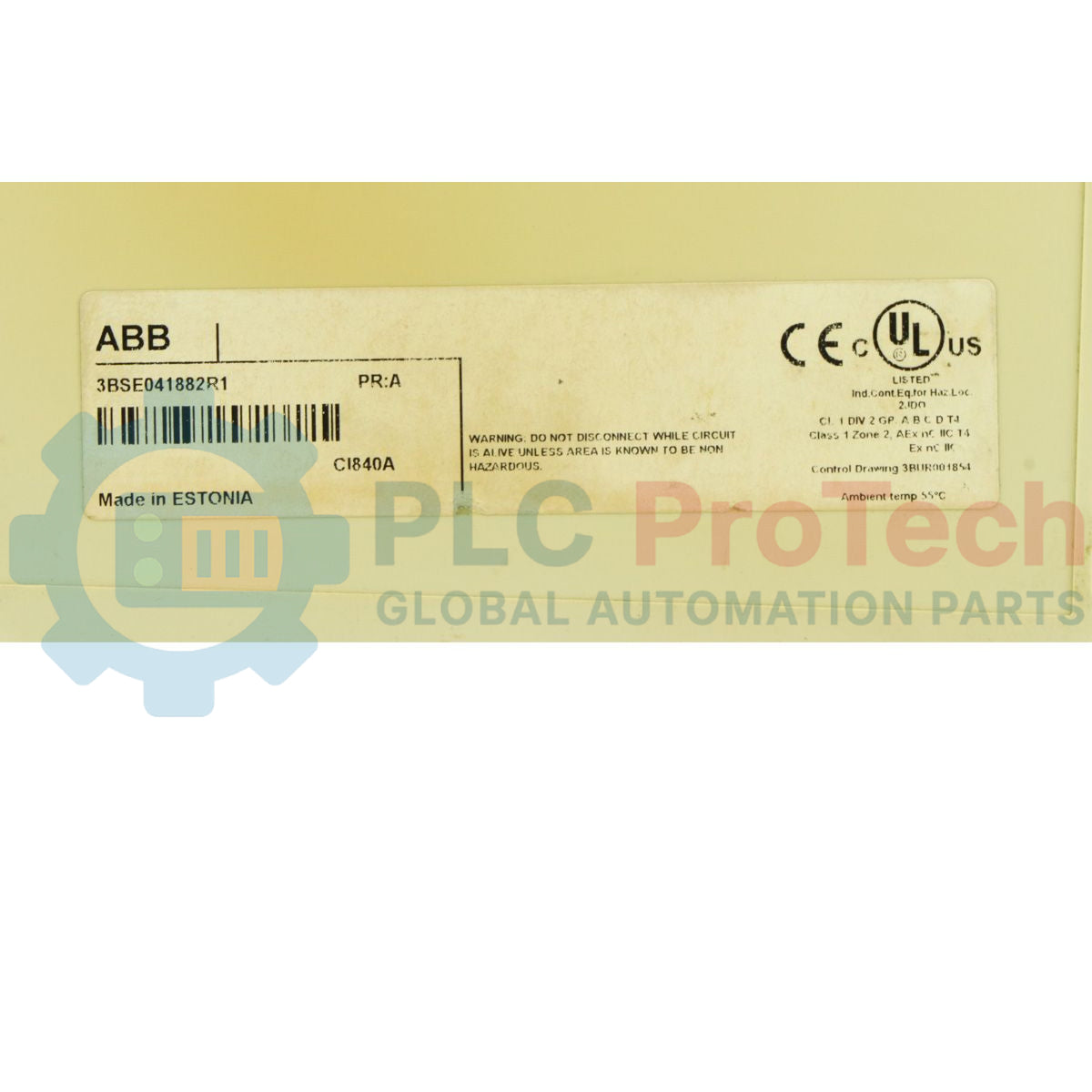
Managing cyclic and acyclic fieldbus communications within distributed automation topologies, the ABB CI840A 3BSE041882R1 serves as a high-speed PROFIBUS DP-V1 master/slave link module for the S800 I/O system. This module facilitates continuous data exchange between the host controller and remote I/O devices, translating protocols with deterministic accuracy. When paired with a compatible Module Termination Unit (MTU), it supports full 1+1 media and hardware redundancy, making it highly suitable for mission-critical industrial processes. The compact design mounts directly onto standard DIN rails via the termination unit, allowing easy integration into existing System 800xA and Compact Product Suite infrastructures.
Features
-
PROFIBUS DP-V1 Connectivity: Handles cyclic process data alongside acyclic parameter, diagnostic, and alarm information.
-
Hardware Redundancy Support: Enables dual-line, hot-standby redundancy setups when combined with TU846 or TU847 terminal blocks.
-
Hot-Swappable Operation: Modules can be replaced under power without interrupting active communication bus traffic (when in redundant configuration).
-
No Internal Batteries Required: Minimizes routine maintenance tasks and environmental footprint.
-
RoHS & Environmental Compliance: Meets strict European standards for hazardous materials reduction.
Applications
- S800 distributed I/O systems in process control architectures.
- System 800xA and Compact Product Suite control networks.
- High-availability systems such as petrochemical plants, power generation facilities, and water treatment operations.
Technical Specifications
| Parameter |
Value |
| Manufacturer |
ABB |
| Model / Part Number |
CI840A / 3BSE041882R1 |
| Protocol Type |
PROFIBUS DP-V1 (Master/Slave) |
| Redundancy Options |
1+1 Line & Module Redundancy (requires TU846/TU847 MTU) |
| Module Dimensions (W x H x D) |
54 mm x 119 mm x 96 mm |
| Net Weight |
0.2 kg |
| Shipping Weight (Calculated) |
0.35 kg |
| Package Dimensions (Calculated) |
150 mm x 100 mm x 130 mm |
| WEEE Category |
5 (Small Equipment under 50 cm) |
| HS Code / Customs Tariff Number |
85176200 |
Empirical Engineering Insights
Alternative Models & Compatibility
The CI840A (3BSE041882R1) acts as a direct form-factor replacement for the legacy CI840 module. However, when configured in redundant pairs on a TU847 Module Termination Unit, both modules must run identical firmware and hardware revisions. Mixing a legacy CI840 and a newer CI840A in the same redundant base will cause failover configuration mismatch errors, preventing the secondary unit from taking control during a primary unit fault.
Application Pitfalls & Engineering Notes
Ensure that the PROFIBUS networks are terminated correctly at the extreme ends of the physical trunks. In redundant setups, activating internal active termination on intermediate nodes or on a non-terminal TU847 block will severely degrade signal integrity, causing intermittent communication dropouts and CRC errors. Additionally, check the module power distribution; sudden voltage dips on the auxiliary 24V DC feed below 19.2V DC will trigger an automatic module reset.
Commissioning & Wiring Tips
The station address for the PROFIBUS interface must be selected using the hardware rotary switches located on the front of the module housing. This address is only read during the initial power-on boot sequence. If you adjust the rotary switches while the module is powered, the change will not take effect until the module is fully power-cycled or soft-rebooted via the controller software.
Installation Guidelines
CRITICAL WARNING: De-energize all primary 24V DC power feeds before inserting or removing the module from its termination unit. Although hot-swapping is physically possible during dual-module redundant operation, conducting hot-swapping on a single-channel configuration will instantly drop all connected S800 I/O modules, resulting in immediate loss of field signal feedback and process shutdown.
1
Set the correct PROFIBUS address using the hardware rotary switches located on the front face of the CI840A module.
2
Align the module guides with the matching slot on the TU846 or TU847 Module Termination Unit.
3
Firmly slide the module into the terminal base until the locking tabs snap into place. Secure the locking mechanism to prevent vibration displacement.
4
Connect the DB9 PROFIBUS network cable to the termination unit and apply 24V DC power. Verify that the 'PWR' and 'RUN' LED status lights show green.