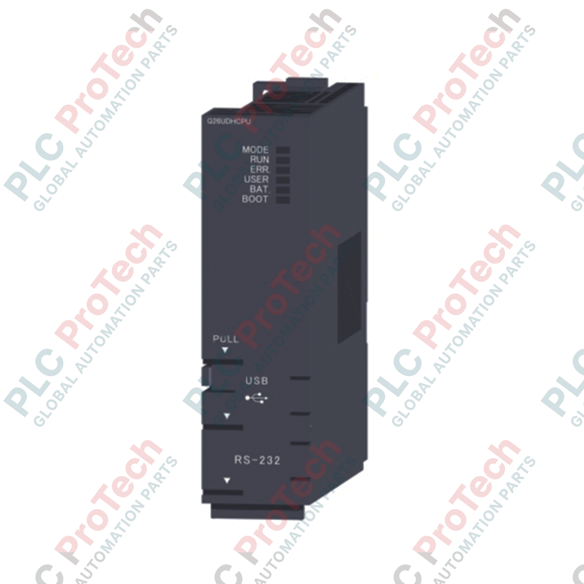
Description
Designed for high-speed, multi-disciplinary industrial control, the Mitsubishi Electric Q26UDHCPU represents the high-tier processing tier of the MELSEC Q Series programmable logic controller platform. This module executes basic logical operations at an ultra-fast instruction speed of 9.5 ns, allowing control engineers to run highly complex control loops without cycle time degradation. It features a generous 260 K steps program capacity alongside extensive device memory allocations, making it highly suitable for demanding multi-CPU configurations and data-intensive manufacturing applications.
Features
-
Ultra-High-Speed Execution: Processes basic LD instructions in 9.5 ns and MOV instructions in 19 ns for deterministic cycle execution.
-
Substantial Memory Architecture: Features 1040 KB of program memory, 1280 KB of standard RAM, and 4096 KB of standard ROM.
-
Multi-Language Programming: Supports Structured Text (ST), Ladder Diagrams (LD), Sequential Function Charts (SFC/MELSAP), and Function Blocks.
-
Advanced Device Range: Manages up to 8192 total device points and 4096 physical input/output points.
-
Multi-CPU Support: Integrates high-speed communication areas (32 KB shared memory) for synchronized parallel processing with up to four CPUs.
Applications
- High-speed multi-axis packaging and bottling machinery.
- Automotive assembly line body-shop controllers.
- Large-scale municipal water treatment plant processing units.
- Semiconductor fabrication tool coordination and material handling.
Technical Specifications
| Parameter |
Value |
| Manufacturer |
Mitsubishi Electric |
| Model Code |
Q26UDHCPU |
| Control Method |
Stored program iteration operation |
| I/O Control Method |
Refresh method (Direct access I/O possible) |
| LD Instruction Execution Speed |
9.5 ns |
| Program Capacity |
260 K steps (1040 KB) |
| Standard RAM (Drive 3) |
1280 KB |
| Standard ROM (Drive 4) |
4096 KB |
| Internal Current Consumption (5 VDC) |
0.39 A |
| Operating Ambient Temperature |
0 to 55 degC |
| Storage Ambient Temperature |
-25 to 75 degC |
| Dimensions (H x W x D) |
98 mm x 27.4 mm x 89.3 mm |
| Net Weight |
0.20 kg |
| Shipping Weight (Calculated) |
1.20 kg |
Empirical Engineering Insights
Alternative Models & Compatibility
This universal model acts as a direct, high-capacity upgrade path from legacy Q-series processors such as the Q25HCPU. When migrating projects to this module, verify that your GX Works2 or GX Developer programming software is updated to support the extended device points and structural changes. Note that the Universal model supports newer SRAM, Flash, and ATA memory cards which may differ from older High-Performance model interfaces.
Application Pitfalls & Engineering Notes
When utilizing this processor in complex multi-CPU configurations, keep in mind that the CPU shared memory high-speed communication area is limited to 32 KB. Exceeding this limit will force the system to route communications through standard CPU shared memory, which adds latency. Ensure that the total current draw of all modules on your base unit does not exceed the maximum rated output of the chosen Q-series power supply module, especially considering the unit's native 0.39 A draw at 5 VDC.
Commissioning & Wiring Tips
When installing memory cards (e.g., SRAM cards), always perform format routines through the GX Works2 interface prior to data mapping. Do not remove or insert memory cards while the CPU is powered on to prevent data corruption. Always ensure the backup battery is fully functional and connected if you are utilizing the standard RAM (Drive 3) or latch relays to store critical recipe parameters during power-off states.
Installation Guidelines
CRITICAL WARNING
Shut down all main electrical disconnects powering the PLC rack before attempting to install or remove this CPU module. Failure to de-energize the backplane may cause structural damage to the connector pins, produce system fault codes, or lead to immediate hardware failure.
1
Align the module's lower hook onto the base unit's guide groove.
2
Push the top of the module firmly onto the base plate until the module lock clicks into position.
3
Secure the module to the base unit using the integrated mounting screw (M3 screw, torque to 0.36 to 0.48 N-m).
4
Connect the communication and programming cables to the front-panel interfaces prior to powering up.