ABB

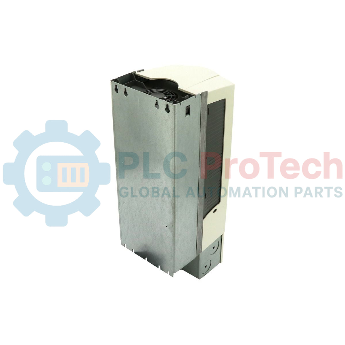
ABB ACS550-01-031A-4 ACS550 Variable Frequency Drive

SKU ACS550-01-031A-4

Disponibile
  • 12-month warranty
  • Free returns within 30 days
  • Manufacturer: ABB
  • Product No.: ACS550-01-031A-4
  • Origin Sweden
  • Product Type: Variable Frequency Drives
  • Barcode: 85044086
  • Payment: T/T, Western Union
  • Weight: 16.0 kg
  • Dimensions: 583 mm x 203 mm x 231 mm
  • Shipping port: Xiamen
  • Warranty: 12 months

Tags

Quantità

Product Description

Description

Managing three-phase motor performance in demanding automation systems is optimized using the ABB ACS550-01-031A-4 variable frequency drive, which supplies a nominal output current of 31 Amps and 15 kW (20 HP) of normal-duty shaft power. Engineered as an industrial-grade AC drive, this model operates on an input voltage range of 380 to 480 V AC, ensuring steady performance under fluctuating line conditions. The physical frame incorporates an integrated patented swinging choke design that significantly reduces supply line harmonics under both partial and full load conditions. Encased in a protective IP21 enclosure class, it is optimized for clean, wall-mounted indoor vertical installations, enabling close-coupled motor speed and torque regulation across various mechanical processes.

Features

  • Advanced scalar and vector motor control models to accommodate both constant and variable torque loads.
  • Integrated swinging choke design providing up to 25% lower low-frequency harmonics compared to traditional reactors.
  • Built-in standard Modbus RTU interface with expansion slots for optional fieldbus communication adapters.
  • Internal EMC filter as a standard component to limit electromagnetic emission and radio frequency interference.
  • Dedicated assistant control panel featuring multi-language support, real-time diagnostic helpers, and parameter backup capabilities.
  • Coated electronic circuit boards for improved reliability and resistance to industrial dust and ambient humidity.

Applications

  • Centrifugal pumps and high-volume water distribution booster systems.
  • Industrial ventilation fans, exhaust systems, and variable air-volume (VAV) air-handling units.
  • Bulk material handling conveyors and packaging line sorting belts.
  • Rotary screw air compressors and positive displacement industrial pumps.

Technical Specifications

Parameter Specification Value
Manufacturer ABB
Model Code ACS550-01-031A-4
Product Series ACS550 Standard Drive
Input Voltage Range 380 to 480 V AC (+10% / -15%)
Number of Phases 3-Phase
Input Frequency 48 to 63 Hz
Nominal Output Current (Normal Use) 31.0 Amps
Nominal Output Current (Heavy Duty) 24.6 Amps
Output Power (Normal Use) 15 kW (20 HP)
Output Power (Heavy Duty) 11 kW (15 HP)
Frame Size R3
Enclosure Class IP21 (UL Type 1)
Ambient Operating Temperature -15 to +40 degC (No frost allowed; up to +50 degC with current derating)
Efficiency (at nominal power) 97.5%
Dimensions (H x W x D) 583 mm x 203 mm x 231 mm
Net Shipping Weight 16.00 kg
Country of Origin Finland

Connections and Interfaces

Terminal Block Designation Functional Assignment / Wiring Parameter
U1, V1, W1 3-Phase AC mains input power connection terminals
U2, V2, W2 3-Phase AC variable frequency output to induction motor
UDC+, UDC- Internal DC intermediate bus connections (for dynamic brake chopper modules)
PE (Grounding Terminals) Protective Earth terminals for input feed and output motor cable shield
X1-1 to X1-6 (Analog I/O) AI1 (Speed Ref), AI2 (Process Ref), AO1 (Frequency), AO2 (Current), 10V Reference, AGND
X1-9 to X1-18 (Digital I/O) DI1 (Start/Stop), DI2 (Fwd/Rev), DI3 to DI6 (Preset Speeds / Ramp select), +24V Aux Output
X1-19 to X1-27 (Relay Outputs) Three programmable relay outputs (RO1: Ready, RO2: Running, RO3: Fault / Active Disturbance)

Empirical Engineering Insights

Alternative Models & Compatibility

This R3-frame unit functions as a direct drop-in replacement for older ACS550-01-031A-4 drives. If migrating parameter configurations via the assistant control panel (ACS-CP-A) from older versions of the drive, ensure that the target drive firmware matches the source version to prevent "Incompatible Parameter" transfer faults.

Application Pitfalls & Engineering Notes

Frame R3 thermal design relies on efficient forced-air convection. The cooling fan draws air from the bottom; thus, maintaining a minimum clearance of 200 mm above and below the VFD chassis is mandatory. Running this model inside unventilated, high-heat panels without dynamic thermal calculation will cause overtemperature faults (Fault 9: MOTOR OVERTEMP or Fault 3: DEV OVERTEMP) due to heat accumulation on the internal heatsink.

Commissioning & Wiring Tips

When running on IT networks (ungrounded delta systems), the internal EMC filter must be disconnected by removing the internal EMC grounding screw. Failure to disconnect this filter on an ungrounded system will ground the drive's internal capacitors, causing fatal damage to the input varistors and input bridge rectifier.

Installation Guidelines

CRITICAL WARNING: HIGH VOLTAGE HAZARD

Isolate all electrical feeds prior to removing the front enclosure cover. After de-energizing, wait a minimum of 5 minutes for the internal DC intermediate bus capacitors to discharge. Measure voltage across terminals UDC+ and UDC- using a calibrated voltmeter to ensure potential is below 50 V DC before starting physical service or terminal block termination.

1

Mount the drive vertically to a flat, non-flammable backplate within an enclosure designed to meet the site ambient requirements.

2

Run input power cables and output motor cables in separate steel conduits to mitigate high-frequency cross-coupling and electrical noise injection.

3

Terminate 3-phase incoming power to U1, V1, W1 and dynamic brake/motor lines to U2, V2, W2. Torque terminals according to standard frame R3 specification requirements.

4

Ground the drive frame using the dedicated PE grounding terminal, and connect the low-voltage control analog/digital signaling using shielded twisted pair cables terminated to the control terminal block.

Shipping & Returns

Global Express Shipping

  • Standard Delivery: 4–6 business days via DHL, FedEx, and UPS.
  • Express Dispatch: Same-day dispatch for in-stock orders placed before 2:00 PM (GMT+8).
  • Worldwide Coverage: Serving over 150 countries.

Returns & Warranty

  • 30-Day Guarantee: Returns accepted for in-stock products in original, factory-sealed packaging.
  • 12-Month Warranty: Every industrial component is backed by our technical warranty.
FAQ
What does the '031A' indicate in the ACS550-01-031A-4 model code?
It specifies the normal-duty nominal output current rating of 31.0 Amps, which is suitable for standard variable torque motor loads up to 15 kW (20 HP).
Can I operate this ACS550 drive on a 230V or single-phase supply network?
No. This model requires a 3-phase input voltage supply of 380 to 480 V AC. Operating on single-phase will trigger phase loss trip codes, and lower voltages will cause undervoltage faults.
What is the physical frame size of this specific model?
The ACS550-01-031A-4 has a physical Frame Size of R3, which governs its dimensions, weight, thermal footprint, and mounting patterns.
How do I resolve a Ground Loop or Earth Fault (Fault Code F0016) during startup?
Verify the insulation of the motor and motor cable using a megohmmeter (with VFD disconnected). If insulation is fine, inspect motor cable routing for parallel cable capacitive coupling or check that the internal EMC filter grounding screw is in the correct configuration for your local grounding system.
Reviews

ACS550-01-031A-4

Stock & lead time on request

Call
1 su 6

ABB ACS550-01-031A-4 ACS550 Variable Frequency Drive

Only 5 item(s) left in stock
  • Manufacturer: ABB

  • Product No.: ACS550-01-031A-4

  • Country of origin:Sweden

  • Product Type: Variable Frequency Drives

  • Barcode: 85044086

  • Payment: T/T, Western Union

  • Weight: 16000g

  • Dimensions: 583 mm x 203 mm x 231 mm

  • Shipping port: Xiamen

  • Warranty: 12 months

Quantità
Visualizza dettagli completi

Product Description

Description

Managing three-phase motor performance in demanding automation systems is optimized using the ABB ACS550-01-031A-4 variable frequency drive, which supplies a nominal output current of 31 Amps and 15 kW (20 HP) of normal-duty shaft power. Engineered as an industrial-grade AC drive, this model operates on an input voltage range of 380 to 480 V AC, ensuring steady performance under fluctuating line conditions. The physical frame incorporates an integrated patented swinging choke design that significantly reduces supply line harmonics under both partial and full load conditions. Encased in a protective IP21 enclosure class, it is optimized for clean, wall-mounted indoor vertical installations, enabling close-coupled motor speed and torque regulation across various mechanical processes.

Features

  • Advanced scalar and vector motor control models to accommodate both constant and variable torque loads.
  • Integrated swinging choke design providing up to 25% lower low-frequency harmonics compared to traditional reactors.
  • Built-in standard Modbus RTU interface with expansion slots for optional fieldbus communication adapters.
  • Internal EMC filter as a standard component to limit electromagnetic emission and radio frequency interference.
  • Dedicated assistant control panel featuring multi-language support, real-time diagnostic helpers, and parameter backup capabilities.
  • Coated electronic circuit boards for improved reliability and resistance to industrial dust and ambient humidity.

Applications

  • Centrifugal pumps and high-volume water distribution booster systems.
  • Industrial ventilation fans, exhaust systems, and variable air-volume (VAV) air-handling units.
  • Bulk material handling conveyors and packaging line sorting belts.
  • Rotary screw air compressors and positive displacement industrial pumps.

Technical Specifications

Parameter Specification Value
Manufacturer ABB
Model Code ACS550-01-031A-4
Product Series ACS550 Standard Drive
Input Voltage Range 380 to 480 V AC (+10% / -15%)
Number of Phases 3-Phase
Input Frequency 48 to 63 Hz
Nominal Output Current (Normal Use) 31.0 Amps
Nominal Output Current (Heavy Duty) 24.6 Amps
Output Power (Normal Use) 15 kW (20 HP)
Output Power (Heavy Duty) 11 kW (15 HP)
Frame Size R3
Enclosure Class IP21 (UL Type 1)
Ambient Operating Temperature -15 to +40 degC (No frost allowed; up to +50 degC with current derating)
Efficiency (at nominal power) 97.5%
Dimensions (H x W x D) 583 mm x 203 mm x 231 mm
Net Shipping Weight 16.00 kg
Country of Origin Finland

Connections and Interfaces

Terminal Block Designation Functional Assignment / Wiring Parameter
U1, V1, W1 3-Phase AC mains input power connection terminals
U2, V2, W2 3-Phase AC variable frequency output to induction motor
UDC+, UDC- Internal DC intermediate bus connections (for dynamic brake chopper modules)
PE (Grounding Terminals) Protective Earth terminals for input feed and output motor cable shield
X1-1 to X1-6 (Analog I/O) AI1 (Speed Ref), AI2 (Process Ref), AO1 (Frequency), AO2 (Current), 10V Reference, AGND
X1-9 to X1-18 (Digital I/O) DI1 (Start/Stop), DI2 (Fwd/Rev), DI3 to DI6 (Preset Speeds / Ramp select), +24V Aux Output
X1-19 to X1-27 (Relay Outputs) Three programmable relay outputs (RO1: Ready, RO2: Running, RO3: Fault / Active Disturbance)

Empirical Engineering Insights

Alternative Models & Compatibility

This R3-frame unit functions as a direct drop-in replacement for older ACS550-01-031A-4 drives. If migrating parameter configurations via the assistant control panel (ACS-CP-A) from older versions of the drive, ensure that the target drive firmware matches the source version to prevent "Incompatible Parameter" transfer faults.

Application Pitfalls & Engineering Notes

Frame R3 thermal design relies on efficient forced-air convection. The cooling fan draws air from the bottom; thus, maintaining a minimum clearance of 200 mm above and below the VFD chassis is mandatory. Running this model inside unventilated, high-heat panels without dynamic thermal calculation will cause overtemperature faults (Fault 9: MOTOR OVERTEMP or Fault 3: DEV OVERTEMP) due to heat accumulation on the internal heatsink.

Commissioning & Wiring Tips

When running on IT networks (ungrounded delta systems), the internal EMC filter must be disconnected by removing the internal EMC grounding screw. Failure to disconnect this filter on an ungrounded system will ground the drive's internal capacitors, causing fatal damage to the input varistors and input bridge rectifier.

Installation Guidelines

CRITICAL WARNING: HIGH VOLTAGE HAZARD

Isolate all electrical feeds prior to removing the front enclosure cover. After de-energizing, wait a minimum of 5 minutes for the internal DC intermediate bus capacitors to discharge. Measure voltage across terminals UDC+ and UDC- using a calibrated voltmeter to ensure potential is below 50 V DC before starting physical service or terminal block termination.

1

Mount the drive vertically to a flat, non-flammable backplate within an enclosure designed to meet the site ambient requirements.

2

Run input power cables and output motor cables in separate steel conduits to mitigate high-frequency cross-coupling and electrical noise injection.

3

Terminate 3-phase incoming power to U1, V1, W1 and dynamic brake/motor lines to U2, V2, W2. Torque terminals according to standard frame R3 specification requirements.

4

Ground the drive frame using the dedicated PE grounding terminal, and connect the low-voltage control analog/digital signaling using shielded twisted pair cables terminated to the control terminal block.

What does the '031A' indicate in the ACS550-01-031A-4 model code?

It specifies the normal-duty nominal output current rating of 31.0 Amps, which is suitable for standard variable torque motor loads up to 15 kW (20 HP).

Can I operate this ACS550 drive on a 230V or single-phase supply network?

No. This model requires a 3-phase input voltage supply of 380 to 480 V AC. Operating on single-phase will trigger phase loss trip codes, and lower voltages will cause undervoltage faults.

What is the physical frame size of this specific model?

The ACS550-01-031A-4 has a physical Frame Size of R3, which governs its dimensions, weight, thermal footprint, and mounting patterns.

How do I resolve a Ground Loop or Earth Fault (Fault Code F0016) during startup?

Verify the insulation of the motor and motor cable using a megohmmeter (with VFD disconnected). If insulation is fine, inspect motor cable routing for parallel cable capacitive coupling or check that the internal EMC filter grounding screw is in the correct configuration for your local grounding system.

Global Express Shipping

  • Standard Delivery: 4-6 Business Days via DHL, FedEx, and UPS.
  • Express Dispatch: Same-day dispatch for in-stock orders placed before 2:00 PM (GMT+8).
  • Worldwide Coverage: Serving over 150 countries, including rapid delivery to Saudi Arabia and UAE.

Returns & Warranty

  • 30-Day Guarantee: Returns accepted for in-stock products in original, factory-sealed packaging.
  • 12-Month Warranty: Every industrial component is backed by our professional technical warranty.

Orders are processed and delivered Monday-Friday (excluding public holidays).


For full eligibility, restocking fees, and international return details, please view our official Refund & Return Policy .

TECHNICAL SPECIFICATIONS

Country of origin
Sweden

Technical knowledge

1756-L73 Firmware Upgrade Guide: v19 vs v21/v31 Decision

Replacing a 1756-L73 does not automatically mean upgrading its firmware. This guide compares v19.013, v21.011 and v31.011, focusing on project compatibility, HMI communications, legacy networks and...

Implementing 3-Switch XOR Ladder Logic with Internal Bit

Implement a 3-SPST switch XOR light circuit in LogixPro or RSLogix 500 using an internal relay bit. Includes truth tables, boolean equations, and verified.

Building a Modbus RTU Network with CompactLogix and DeltaV

Integrate Allen-Bradley CompactLogix, Caterpillar ATS, and generators into DeltaV DCS over Modbus RTU. Covers ProSoft MVI69-MCM, Miille DIN266 gateways.

ONS Instruction Not Energizing OTE in Studio 5000 Ladder Logic

ONS instruction fires but the OTE coil never latches in Studio 5000 because the one-shot is only true for one scan. Use OTL/OTU or seal-in logic instead.

Kinetix 5500 EtherNet/IP Network Switch Requirements and Topology

Configure Allen-Bradley Kinetix 5500 servo drives on EtherNet/IP. Covers CIP Sync, IEEE 1588 V2 timing, Stratix selection, DLR topology, and HMI.

Moving Average Filtering in DCS and PLC Analog Control

A moving-average filter is the sliding-window smoother most instrument engineers drop into DCS and PLC analog paths. Here is how the window works, how N and sample time set lag, and when a...