General Electric

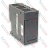
GE Fanuc IC695PSD140 PACSystems RX3i Multi-Purpose Power Supply

SKU IC695PSD140

Disponibile
  • 12-month warranty
  • Free returns within 30 days
  • Manufacturer: General Electric
  • Product No.: IC695PSD140
  • Origin United States
  • Product Type: Power Supply
  • Barcode: 8537101190
  • Payment: T/T, Western Union
  • Weight: 0.25 kg
  • Dimensions: 3.5cm x 13.5cm x 13.5cm
  • Shipping port: Xiamen
  • Warranty: 12 months

Tags

Product Documentation

Technical Datasheet (PDF) Complete specifications and technical drawings.

Technical Datasheet

GE Fanuc IC695PSD140 PACSystems RX3i Multi-Purpose Power Supply

Quantità

Product Description

Description

The multi-purpose power supply module operates as a dedicated chassis power distribution source designed for high-availability industrial systems. The IC695PSD140 converts an unregulated input voltage range from 18 to 30 VDC into three stable output rails to drive internal backplane logic and field-side components. Engineered for structural compatibility with the PACSystems RX3i hardware platform, this component interfaces directly inside a universal backplane assembly, providing power delivery for process logic controllers and expansion rack nodes. The unit supports advanced configuration arrangements including load-sharing networks and active redundancy deployments, making it suitable for critical infrastructure applications such as power plant distribution, automotive assembly rows, and continuous wastewater processing plants.

Features

  • Provides three internal voltage outputs: a +5.1 VDC rail, a +3.3 VDC rail, and a +24 VDC output dedicated to powering external relay module circuits.
  • Supports dual-redundant or load-sharing multi-module installation with up to four identical supplies operating in a single backplane assembly.
  • Equipped with front-facing diagnostics including dedicated status LEDs for power indication, generic hardware faults, internal overtemperature, and load circuit exceptions.
  • Features an integrated hardware latching design that switches the module completely off during overload conditions to protect adjacent processing units.
  • Contains a physical front-panel toggle switch situated behind a protection door to toggle supply outputs without interrupting incoming line utility feeds.

Applications

  • Redundant Power Distribution Enclosures
  • PACSystems RX3i Main and Expansion Chassis Platforms
  • Load-Sharing Control System Nodes
  • High-Density Field Output Relay Driver Arrays

Technical Specifications

Parameter Configuration and Rating Value
Manufacturer GE Fanuc 
Model IC695PSD140 
Series Platform PACSystems RX3i 
Product Type Multi-Purpose Power Supply 
Nominal Rated Voltage 24 VDC 
Input Voltage Range 18 to 30 VDC 
Input Power Consumption 60 Watts maximum at full load 
Maximum Output Power 40 Watts total (5.1 VDC and 3.3 VDC combined rails) 
5.1 VDC Output Current 0 to 6 Amps (30 Watts maximum) 
3.3 VDC Output Current 0 to 9 Amps (30 Watts maximum) 
Inrush Current Limits 4 Amps maximum for a 100 millisecond duration 
Output Ripple and Noise 50 mV maximum on all output paths 
Ride-Through Interruption Time 10 ms maximum duration 
Isolation Barrier None 
Overcurrent Safety Thresholds 5.1 VDC limited to 7 Amps; 3.3 VDC limited to 10 Amps 
Wiring Terminal Capacity Accommodates 14 AWG to 24 AWG copper wire paths 
Terminal Current Rating 6 Amps max 
Maximum Rack Grouping Up to 4 modules per Universal Backplane assembly 

Connections and Interfaces

Terminal Alignment Mark Functional Wiring Assignment
+ Positive DC Input Terminal Link 1 
+ Positive DC Input Terminal Link 2 (Daisy-Chain Option) 
- Negative DC Input Terminal Link 1 
- Negative DC Input Terminal Link 2 (Daisy-Chain Option) 
Ground Symbol (Top) Core Frame Ground Enclosure Reference Connection 
Ground Symbol (Bottom) Secondary Internal Protection Return Path 
Surge Symbol Internal MOV Disconnect Overvoltage Link Point 

Installation Guidelines

  • Module Backplane Seating: Align the supply module rails directly into the dedicated slot guides of a PACSystems RX3i Universal Backplane. Slide the module firmly backward until the rear connector is entirely mated with the backplane connectors.
  • Terminal Wiring and Torque: Strip incoming 14 to 22 AWG copper field wires rated for 75 degC environments. Insert a single conductor into each block cage and tighten the integrated screw terminals to a standard torque specification of 0.5 N-m (4.4 in-lb).
  • Redundancy Polarity Alignment: When grouping multiple modules onto a single external DC source, maintain identical connection polarity across every active supply. Any difference in ground or input line potential will cause machine damage or immediate fault trips.
  • Overvoltage Protection Disconnect: For system Hi-pot testing routines, remove the user-installed jumper strap that bridges the lower terminal path to frame ground. Reinstall this grounding strap immediately after testing to restore internal surge protection loops.
Shipping & Returns

Global Express Shipping

  • Standard Delivery: 4–6 business days via DHL, FedEx, and UPS.
  • Express Dispatch: Same-day dispatch for in-stock orders placed before 2:00 PM (GMT+8).
  • Worldwide Coverage: Serving over 150 countries.

Returns & Warranty

  • 30-Day Guarantee: Returns accepted for in-stock products in original, factory-sealed packaging.
  • 12-Month Warranty: Every industrial component is backed by our technical warranty.
FAQ
Can this power supply module be combined with an IC695PSD040 unit in redundancy mode?
No, this power supply is strictly incompatible with IC695PSD040 or IC695PSA040 modules when operating in redundant or increased capacity arrangements. Attempting to mix these models can result in severe equipment damage.
What is the continuous operational behavior of the unit when an overcurrent condition occurs?
When an overload or output short circuit is detected, the supply automatically executes a protective shutdown and latches off. To clear this latched fault state and restart the outputs, the primary input power must be completely cycled.
What does an amber indication on the main front-panel POWER LED signify?
An amber POWER LED indicates that primary input voltage is successfully applied to the module's input terminals, but the integrated front-panel ON/OFF switch remains in the off position.
Is this specific multi-purpose power supply module compatible with floating or positive grounded distribution networks?
No, this module features a non-isolated electrical design and is explicitly incompatible with floating or positive grounded industrial power distribution networks.
Reviews

IC695PSD140

Stock & lead time on request

Call
1 su 3

GE Fanuc IC695PSD140 PACSystems RX3i Multi-Purpose Power Supply

Only 4 item(s) left in stock
  • Manufacturer: General Electric

  • Product No.: IC695PSD140

  • Country of origin:United States

  • Product Type: Power Supply

  • Barcode: 8537101190

  • Payment: T/T, Western Union

  • Weight: 250g

  • Dimensions: 3.5cm x 13.5cm x 13.5cm

  • Shipping port: Xiamen

  • Warranty: 12 months

Quantità
Visualizza dettagli completi

Product Description

Description

The multi-purpose power supply module operates as a dedicated chassis power distribution source designed for high-availability industrial systems. The IC695PSD140 converts an unregulated input voltage range from 18 to 30 VDC into three stable output rails to drive internal backplane logic and field-side components. Engineered for structural compatibility with the PACSystems RX3i hardware platform, this component interfaces directly inside a universal backplane assembly, providing power delivery for process logic controllers and expansion rack nodes. The unit supports advanced configuration arrangements including load-sharing networks and active redundancy deployments, making it suitable for critical infrastructure applications such as power plant distribution, automotive assembly rows, and continuous wastewater processing plants.

Features

  • Provides three internal voltage outputs: a +5.1 VDC rail, a +3.3 VDC rail, and a +24 VDC output dedicated to powering external relay module circuits.
  • Supports dual-redundant or load-sharing multi-module installation with up to four identical supplies operating in a single backplane assembly.
  • Equipped with front-facing diagnostics including dedicated status LEDs for power indication, generic hardware faults, internal overtemperature, and load circuit exceptions.
  • Features an integrated hardware latching design that switches the module completely off during overload conditions to protect adjacent processing units.
  • Contains a physical front-panel toggle switch situated behind a protection door to toggle supply outputs without interrupting incoming line utility feeds.

Applications

  • Redundant Power Distribution Enclosures
  • PACSystems RX3i Main and Expansion Chassis Platforms
  • Load-Sharing Control System Nodes
  • High-Density Field Output Relay Driver Arrays

Technical Specifications

Parameter Configuration and Rating Value
Manufacturer GE Fanuc 
Model IC695PSD140 
Series Platform PACSystems RX3i 
Product Type Multi-Purpose Power Supply 
Nominal Rated Voltage 24 VDC 
Input Voltage Range 18 to 30 VDC 
Input Power Consumption 60 Watts maximum at full load 
Maximum Output Power 40 Watts total (5.1 VDC and 3.3 VDC combined rails) 
5.1 VDC Output Current 0 to 6 Amps (30 Watts maximum) 
3.3 VDC Output Current 0 to 9 Amps (30 Watts maximum) 
Inrush Current Limits 4 Amps maximum for a 100 millisecond duration 
Output Ripple and Noise 50 mV maximum on all output paths 
Ride-Through Interruption Time 10 ms maximum duration 
Isolation Barrier None 
Overcurrent Safety Thresholds 5.1 VDC limited to 7 Amps; 3.3 VDC limited to 10 Amps 
Wiring Terminal Capacity Accommodates 14 AWG to 24 AWG copper wire paths 
Terminal Current Rating 6 Amps max 
Maximum Rack Grouping Up to 4 modules per Universal Backplane assembly 

Connections and Interfaces

Terminal Alignment Mark Functional Wiring Assignment
+ Positive DC Input Terminal Link 1 
+ Positive DC Input Terminal Link 2 (Daisy-Chain Option) 
- Negative DC Input Terminal Link 1 
- Negative DC Input Terminal Link 2 (Daisy-Chain Option) 
Ground Symbol (Top) Core Frame Ground Enclosure Reference Connection 
Ground Symbol (Bottom) Secondary Internal Protection Return Path 
Surge Symbol Internal MOV Disconnect Overvoltage Link Point 

Installation Guidelines

  • Module Backplane Seating: Align the supply module rails directly into the dedicated slot guides of a PACSystems RX3i Universal Backplane. Slide the module firmly backward until the rear connector is entirely mated with the backplane connectors.
  • Terminal Wiring and Torque: Strip incoming 14 to 22 AWG copper field wires rated for 75 degC environments. Insert a single conductor into each block cage and tighten the integrated screw terminals to a standard torque specification of 0.5 N-m (4.4 in-lb).
  • Redundancy Polarity Alignment: When grouping multiple modules onto a single external DC source, maintain identical connection polarity across every active supply. Any difference in ground or input line potential will cause machine damage or immediate fault trips.
  • Overvoltage Protection Disconnect: For system Hi-pot testing routines, remove the user-installed jumper strap that bridges the lower terminal path to frame ground. Reinstall this grounding strap immediately after testing to restore internal surge protection loops.

Product Documentation

Technical Datasheet (PDF) Complete specifications and technical drawings.

Technical Datasheet

GE Fanuc IC695PSD140 PACSystems RX3i Multi-Purpose Power Supply

Can this power supply module be combined with an IC695PSD040 unit in redundancy mode?

No, this power supply is strictly incompatible with IC695PSD040 or IC695PSA040 modules when operating in redundant or increased capacity arrangements. Attempting to mix these models can result in severe equipment damage.

What is the continuous operational behavior of the unit when an overcurrent condition occurs?

When an overload or output short circuit is detected, the supply automatically executes a protective shutdown and latches off. To clear this latched fault state and restart the outputs, the primary input power must be completely cycled.

What does an amber indication on the main front-panel POWER LED signify?

An amber POWER LED indicates that primary input voltage is successfully applied to the module's input terminals, but the integrated front-panel ON/OFF switch remains in the off position.

Is this specific multi-purpose power supply module compatible with floating or positive grounded distribution networks?

No, this module features a non-isolated electrical design and is explicitly incompatible with floating or positive grounded industrial power distribution networks.

Global Express Shipping

  • Standard Delivery: 4-6 Business Days via DHL, FedEx, and UPS.
  • Express Dispatch: Same-day dispatch for in-stock orders placed before 2:00 PM (GMT+8).
  • Worldwide Coverage: Serving over 150 countries, including rapid delivery to Saudi Arabia and UAE.

Returns & Warranty

  • 30-Day Guarantee: Returns accepted for in-stock products in original, factory-sealed packaging.
  • 12-Month Warranty: Every industrial component is backed by our professional technical warranty.

Orders are processed and delivered Monday-Friday (excluding public holidays).


For full eligibility, restocking fees, and international return details, please view our official Refund & Return Policy .

TECHNICAL SPECIFICATIONS

Color pattern
Black
Country of origin
United States

Technical knowledge

1756-L73 Firmware Upgrade Guide: v19 vs v21/v31 Decision

Replacing a 1756-L73 does not automatically mean upgrading its firmware. This guide compares v19.013, v21.011 and v31.011, focusing on project compatibility, HMI communications, legacy networks and...

Implementazione della logica a scala XOR con 3 interruttori e bit interno

Implementa un circuito luminoso XOR con 3 interruttori SPST in LogixPro o RSLogix 500 utilizzando un bit di relè interno. Include tabelle della verità, equazioni booleane e verifica.

Creazione di una rete Modbus RTU con CompactLogix e DeltaV

Integra Allen-Bradley CompactLogix, Caterpillar ATS e generatori nel DCS DeltaV tramite Modbus RTU. Include i gateway ProSoft MVI69-MCM e Miille DIN266.

Istruzione ONS che non attiva l’OTE nella logica ladder di Studio 5000

L’istruzione ONS si attiva, ma la bobina OTE non rimane mai eccitata in Studio 5000 perché il one-shot è vero solo per una scansione. Usa OTL/OTU oppure una logica di autoritenuta.

Requisiti e topologia dello switch di rete EtherNet/IP Kinetix 5500

Configura i servoazionamenti Allen-Bradley Kinetix 5500 su EtherNet/IP. Include CIP Sync, la temporizzazione IEEE 1588 V2, la selezione degli switch Stratix, la topologia DLR e l’HMI.

Filtraggio con media mobile nei sistemi di controllo analogico DCS e PLC

Un filtro a media mobile è lo smussatore a finestra scorrevole che la maggior parte degli ingegneri della strumentazione inserisce nei percorsi dei segnali analogici di DCS e PLC. Ecco come funziona...