Description
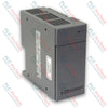
The General Electric IC200PWR001 is a 24VDC nominal input power supply module designed for the VersaMax I/O and control platform. It provides regulated internal backplane power to operate VersaMax Central Processing Units (CPUs), Network Interface Units (NIUs), and adjacent input/output modules across the backplane structure.
Delivering up to 1.5 A of combined output current across dual logic levels of 5VDC and 3.3VDC, the IC200PWR001 allocates up to 0.25 A on the 3.3VDC rail and up to 1.5 A minus the active 3.3V load on the 5VDC rail. When attached directly to a CPU or NIU base carrier, the module functions as the primary power source for the entire local station. In larger multi-module configurations where backplane power demands exceed individual supply limits, the unit can also be deployed as a supplemental power supply installed on an IC200PWB001 Power Supply Booster Carrier.
Technical Specifications
| Parameter |
Specification |
| Product Type |
24VDC Power Supply Module |
| Series / Platform |
VersaMax |
| Input Voltage Range |
18 to 30 VDC (24 VDC nominal) |
| Input Power Consumption |
11 W |
| Holdup Time |
10 ms |
| Inrush Current |
20 A max at 24 VDC (6 ms); 25 A max at 30 VDC (6 ms) |
| Output Voltages |
5 VDC and 3.3 VDC |
| Total Output Current |
1.5 A maximum combined |
| 3.3VDC Output Current |
0.25 A maximum |
| 5VDC Output Current |
1.5 A minus 3.3V current draw maximum |
| Internal Electrical Protection |
Short circuit, overload, reverse polarity |
| Mounting Location |
Snaps onto VersaMax CPU, NIU, or IC200PWB001 Booster Carrier |
| Dimensions (W x H x D) |
49 mm x 133.4 mm x 39 mm (excluding carrier/rail height) |
| Operating Temperature |
0 to 60 degC ambient |
| Country of Origin |
United States |
Installation and Grounding Guidelines
The IC200PWR001 connects directly over the carrier latch post and snaps into the carrier housing. Before insertion, ensure the carrier mechanical latch is in the unlocked position. Align the rear connector pins with the carrier socket and apply firm pressure until the two lower tabs latch securely into the carrier base, then rotate the mechanical latch to the locked position.
DC power wiring is connected to the screw terminals located on the module face. The DC negative terminal (DC-) is tied directly to frame and chassis earth ground internally within the power supply structure. Consequently, floating (ungrounded) DC power sources cannot be used with this module. To comply with industrial electromagnetic and surge protection standards, external Metal Oxide Varistor (MOV) suppression devices must be connected from both positive and negative input terminals to frame ground if not already provided at the enclosure entry line.
Compatibility
The IC200PWR001 is engineered exclusively for the General Electric / Emerson VersaMax modular platform. It is mechanically and electrically compatible with:
- VersaMax CPU carriers and standalone CPU modules (e.g., IC200CPU001, IC200CPUE05)
- VersaMax Network Interface Units including Genius, PROFINET, DeviceNet, and Ethernet NIU stations
- VersaMax Power Supply Booster Carriers (IC200PWB001) for segmented backplane power injection