General Electric

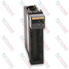
General Electric IC670ALG320 Field Control Analog Output Module

SKU IC670ALG320

Disponibile
  • 12-month warranty
  • Free returns within 30 days
  • Manufacturer: General Electric
  • Product No.: IC670ALG320
  • Origin United States
  • Product Type: Analog Output Module
  • Payment: T/T, Western Union
  • Weight: 0.25 kg
  • Dimensions: 10.5 x 7.0 x 5.0 cm
  • Shipping port: Xiamen
  • Warranty: 12 months

Tags

Product Documentation

Technical Datasheet (PDF) Complete specifications and technical drawings.

Technical Datasheet

General Electric IC670ALG320 Field Control Analog Output Module

Quantità

Product Description

Description

The General Electric IC670ALG320 is a high-performance Field Control Analog Output Module designed for distributed control and I/O applications. This module features four grouped current and voltage analog output channels capable of providing simultaneous current and voltage signals from each D/A converter. It supports flexible output configurations, including 4 to 20 mA and 0 to 20 mA current spans, as well as 0 to 10 V and 0 to 12.5 V voltage spans, easily selectable via jumper placement on the corresponding I/O Terminal Block.

Engineered for seamless integration within the General Electric Field Control architecture, the IC670ALG320 requires a Bus Interface Unit (BIU) to communicate output data to the host processor. It includes a built-in LED indicator visible through the transparent module top to verify correct field and backplane power status. With robust 12-bit digital resolution and built-in transient protection, this module ensures accurate and reliable signal generation for demanding industrial automation environments.

Features

    schemaLocation="features"
  • Four grouped analog output channels supporting simultaneous current and voltage outputs
  • Configurable current output ranges of 0 to 20 mA and 4 to 20 mA
  • Configurable voltage output ranges of 0 to 10 V and 0 to 12.5 V via terminal jumpers
  • Standard 12-bit digital resolution with 4-word (8-byte) analog output data mapping
  • Integrated open-wire diagnostic monitoring functionality on current output channels
  • Robust optical and electrical isolation rated at 1500 VAC for 1 minute to ground and logic
  • Front-panel status LED for quick verification of field and backplane power

Applications

  • Distributed process control systems
  • Analog actuator and valve positioning
  • Interfacing with chart recorders and analog meters
  • Industrial manufacturing and assembly lines
  • Data acquisition and remote telemetry units

Technical Specifications

Parameter Specification
Manufacturer General Electric
Product Number IC670ALG320
Product Family Field Control
Module Type Analog Output Module
Number of Channels 4 Points (Grouped)
Power Supply Voltage Range 20 to 29 VDC (5% max. ripple)
Operating Input Current 180 mA max. (including loop current)
Standby Power Current 80 mA typical (no output)
Module Power Dissipation 1.5 W min. to 4.3 W max.
Digital Resolution 12 bits typical
Current Output Ranges 0–20 mA, 4–20 mA
Voltage Output Ranges 0–10 V, 0–12.5 V
Isolation 1500 VAC for 1 min (ground and logic)
Country of Origin United States

Connections / Interfaces

The IC670ALG320 module interfaces with the system via a compatible Bus Interface Unit and mounts onto an appropriate I/O Terminal Block (such as box terminal, barrier terminal, or wire-to-board connector variants). Field wiring should utilize instrumentation-grade shielded twisted-pair or triad cable with shields grounded at a local panel ground near the module to ensure optimal noise immunity.

Installation Guidelines

  • Ensure all power supplies are turned off before installing or removing the module and terminal blocks.
  • Verify that the correct wire jumpers are installed between the JMP and RET terminals on the I/O Terminal Block when utilizing 0 to 20 mA or 0 to 12.5 V ranges.
  • Ground the module chassis using the chassis ground terminal on the module base for superior electromagnetic interference (EMI) protection.
  • Maintain recommended wire gauges (AWG #14 to AWG #22) depending on the selected terminal block type.
Shipping & Returns

Global Express Shipping

  • Standard Delivery: 4–6 business days via DHL, FedEx, and UPS.
  • Express Dispatch: Same-day dispatch for in-stock orders placed before 2:00 PM (GMT+8).
  • Worldwide Coverage: Serving over 150 countries.

Returns & Warranty

  • 30-Day Guarantee: Returns accepted for in-stock products in original, factory-sealed packaging.
  • 12-Month Warranty: Every industrial component is backed by our technical warranty.
FAQ
How many output channels does the IC670ALG320 provide?
The IC670ALG320 features 4 grouped analog output channels.
What output signal ranges are supported by this module?
The module supports current output ranges of 0 to 20 mA and 4 to 20 mA, and voltage output ranges of 0 to 10 V and 0 to 12.5 V.
How do you change between output ranges on the IC670ALG320?
Output ranges can be configured via software in the Bus Interface Unit and by adding an appropriate wire jumper between the JMP and RET terminals on the I/O Terminal Block.
What power supply is required for module operation?
The module operates on a 20 to 29 VDC power supply range with a maximum 5 percent ripple.
Does the module provide diagnostic capabilities?
Yes, the module features an open-wire diagnostic function that operates on current output channels, as well as a front-panel power status LED.
Reviews

IC670ALG320

Stock & lead time on request

Call
1 su 1

General Electric IC670ALG320 Field Control Analog Output Module

Only 16 item(s) left in stock
  • Manufacturer: General Electric

  • Product No.: IC670ALG320

  • Country of origin:United States

  • Product Type: Analog Output Module

  • Payment: T/T, Western Union

  • Weight: 250g

  • Dimensions: 10.5 x 7.0 x 5.0 cm

  • Shipping port: Xiamen

  • Warranty: 12 months

Quantità
Visualizza dettagli completi

Product Description

Description

The General Electric IC670ALG320 is a high-performance Field Control Analog Output Module designed for distributed control and I/O applications. This module features four grouped current and voltage analog output channels capable of providing simultaneous current and voltage signals from each D/A converter. It supports flexible output configurations, including 4 to 20 mA and 0 to 20 mA current spans, as well as 0 to 10 V and 0 to 12.5 V voltage spans, easily selectable via jumper placement on the corresponding I/O Terminal Block.

Engineered for seamless integration within the General Electric Field Control architecture, the IC670ALG320 requires a Bus Interface Unit (BIU) to communicate output data to the host processor. It includes a built-in LED indicator visible through the transparent module top to verify correct field and backplane power status. With robust 12-bit digital resolution and built-in transient protection, this module ensures accurate and reliable signal generation for demanding industrial automation environments.

Features

    schemaLocation="features"
  • Four grouped analog output channels supporting simultaneous current and voltage outputs
  • Configurable current output ranges of 0 to 20 mA and 4 to 20 mA
  • Configurable voltage output ranges of 0 to 10 V and 0 to 12.5 V via terminal jumpers
  • Standard 12-bit digital resolution with 4-word (8-byte) analog output data mapping
  • Integrated open-wire diagnostic monitoring functionality on current output channels
  • Robust optical and electrical isolation rated at 1500 VAC for 1 minute to ground and logic
  • Front-panel status LED for quick verification of field and backplane power

Applications

  • Distributed process control systems
  • Analog actuator and valve positioning
  • Interfacing with chart recorders and analog meters
  • Industrial manufacturing and assembly lines
  • Data acquisition and remote telemetry units

Technical Specifications

Parameter Specification
Manufacturer General Electric
Product Number IC670ALG320
Product Family Field Control
Module Type Analog Output Module
Number of Channels 4 Points (Grouped)
Power Supply Voltage Range 20 to 29 VDC (5% max. ripple)
Operating Input Current 180 mA max. (including loop current)
Standby Power Current 80 mA typical (no output)
Module Power Dissipation 1.5 W min. to 4.3 W max.
Digital Resolution 12 bits typical
Current Output Ranges 0–20 mA, 4–20 mA
Voltage Output Ranges 0–10 V, 0–12.5 V
Isolation 1500 VAC for 1 min (ground and logic)
Country of Origin United States

Connections / Interfaces

The IC670ALG320 module interfaces with the system via a compatible Bus Interface Unit and mounts onto an appropriate I/O Terminal Block (such as box terminal, barrier terminal, or wire-to-board connector variants). Field wiring should utilize instrumentation-grade shielded twisted-pair or triad cable with shields grounded at a local panel ground near the module to ensure optimal noise immunity.

Installation Guidelines

  • Ensure all power supplies are turned off before installing or removing the module and terminal blocks.
  • Verify that the correct wire jumpers are installed between the JMP and RET terminals on the I/O Terminal Block when utilizing 0 to 20 mA or 0 to 12.5 V ranges.
  • Ground the module chassis using the chassis ground terminal on the module base for superior electromagnetic interference (EMI) protection.
  • Maintain recommended wire gauges (AWG #14 to AWG #22) depending on the selected terminal block type.
Loading product navigation…

Product Documentation

Technical Datasheet (PDF) Complete specifications and technical drawings.

Technical Datasheet

General Electric IC670ALG320 Field Control Analog Output Module

How many output channels does the IC670ALG320 provide?

The IC670ALG320 features 4 grouped analog output channels.

What output signal ranges are supported by this module?

The module supports current output ranges of 0 to 20 mA and 4 to 20 mA, and voltage output ranges of 0 to 10 V and 0 to 12.5 V.

How do you change between output ranges on the IC670ALG320?

Output ranges can be configured via software in the Bus Interface Unit and by adding an appropriate wire jumper between the JMP and RET terminals on the I/O Terminal Block.

What power supply is required for module operation?

The module operates on a 20 to 29 VDC power supply range with a maximum 5 percent ripple.

Does the module provide diagnostic capabilities?

Yes, the module features an open-wire diagnostic function that operates on current output channels, as well as a front-panel power status LED.

Global Express Shipping

  • Standard Delivery: 4-6 Business Days via DHL, FedEx, and UPS.
  • Express Dispatch: Same-day dispatch for in-stock orders placed before 2:00 PM (GMT+8).
  • Worldwide Coverage: Serving over 150 countries, including rapid delivery to Saudi Arabia and UAE.

Returns & Warranty

  • 30-Day Guarantee: Returns accepted for in-stock products in original, factory-sealed packaging.
  • 12-Month Warranty: Every industrial component is backed by our professional technical warranty.

Orders are processed and delivered Monday-Friday (excluding public holidays).


For full eligibility, restocking fees, and international return details, please view our official Refund & Return Policy .

TECHNICAL SPECIFICATIONS

Country of origin
United States

Technical knowledge

Filtrare i segnali PLC rumorosi senza nascondere i guasti reali

Il filtraggio dell’input può stabilizzare i dati del PLC, ma un’eccessiva attenuazione ritarda gli allarmi e maschera i cambiamenti del processo. Scopri come diagnosticare il rumore, scegliere filtri...

SCR o PWM? Scegliere un azionamento per motori CC a spazzole

I sistemi di azionamento SCR e PWM regolano i motori CC a spazzole in modi diversi. Questo confronto analizza la qualità della coppia, l’intervallo di velocità, l’inversione, la frenatura, il rumore...

Come gli inverter industriali generano CA da un bus CC

Gli inverter industriali sintetizzano corrente alternata controllabile da un bus in corrente continua tramite la commutazione e il filtraggio dei semiconduttori. Questa guida illustra i ponti H, la...

Controllo della forza del robot: dal rilevamento del contatto alla stabilità del processo

Il controllo della forza consente a un robot di adattarsi al contatto invece di seguire esclusivamente la posizione. Questa guida confronta gli approcci al rilevamento, le modalità di controllo, i...

Quando la logica a livello di sensore è utile e quando nasconde i rischi

I sensori configurabili possono eseguire decisioni su finestre, latch, ritardi e logica booleana prima che i dati raggiungano un PLC. Il vantaggio è una risposta locale più rapida; il rischio...

Collegamento di GX Simulator a Factory I/O tramite OPC

Una configurazione stabile di messa in servizio virtuale Mitsubishi richiede più della semplice corrispondenza degli indirizzi. Questa guida spiega il percorso dei dati GX Simulator–OPC–Factory I/O,...