


Moving TwinCAT 3 Licenses with C9900-L100: Build and Device Checks
Before moving a TwinCAT 3 license with a Beckhoff C9900-L100, verify the TwinCAT build, XML device description, exact order code and cabinet limits.
Manufacturer: General Electric
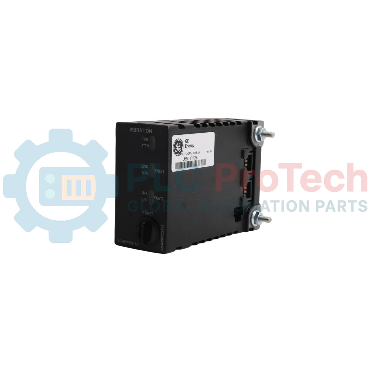
Product No.: IS220PVIBH1A
Country of origin:United States
Product Type: Pacchetto I/O per il monitoraggio delle vibrazioni
Barcode: 8537101190
Payment: T/T, Western Union
Weight: 450g
Dimensions: 3,25" di altezza x 1,65" di larghezza x 4,78" di profondità
Shipping port: Xiamen
Warranty: 12 months
IS220PVIBH1A funziona come componente hardware di interfaccia ad alta affidabilità all'interno della serie di sistemi di controllo turbine Mark VI Speedtronic e Mark VIe di General Electric. Operando con l'acronimo funzionale PVIB, questo specializzato pacchetto I/O per il monitoraggio delle vibrazioni stabilisce una connessione elettronica diretta tra due reti Ethernet indipendenti a 10/100 e una scheda terminale per vibrazioni (TVBA) compatibile. Dal punto di vista architetturale, il modulo è suddiviso in tre livelli principali: una scheda processore principale standardizzata, comune ai componenti Mark VIe distribuiti, una scheda di acquisizione ottimizzata e una struttura dedicata con scheda figlia. Progettato per raccogliere la telemetria transitoria delle strutture dei macchinari, IS220PVIBH1A gestisce tredici canali dinamici ad alta precisione per acquisire informazioni di prossimità, sismiche, di accelerazione e di velocità angolare da diversi sensori industriali. La scheda incorpora una matrice interna di convertitori digitale-analogico (DAC) attraverso le sue intersezioni di segnale differenziale per calibrare i fattori di offset della polarizzazione CC, massimizzando l'intervallo di conversione della logica hardware analogico-digitale (A/D). Supporta pienamente le architetture a ridondanza modulare tripla (TMR) o le configurazioni di monitoraggio simplex, garantendo l'acquisizione continua dei dati sulle vibrazioni senza interrompere gli algoritmi di controllo attivi.
| Parametro | Valore della specifica |
|---|---|
| Produttore | General Electric (GE) |
| Numero di parte | IS220PVIBH1A |
| Acronimo funzionale | PVIB |
| Classificazione della serie di controllo | Framework Mark VI IS200 / Mark VIe Speedtronic |
| Profilo della variante di assemblaggio | Revisione singola del prodotto funzionale di categoria A (originale: pacchetto principale IS220PVIBH1) |
| Scheda base compatibile | Scheda terminale per vibrazioni (TVBA) |
| Canali di segnale totali | Tredici (13) ingressi dinamici differenziali |
| Frequenze fotogrammi selezionabili | 3,125 Hz, 6,25 Hz, 12,5 Hz, 25 Hz, 50 Hz e 100 Hz |
| Alimentazione della sonda del trasduttore | -24 VDC, allocazione di carico costante di 12 mA per trasduttore |
| Tensione minima di modo comune | 5 VDC |
| Intervallo di temperatura ambiente | Da -30 a 65 gradi Celsius |
| Dimensioni di base | 3,25" di altezza x 1,65" di larghezza x 4,78" di profondità |
| Peso dell'unità hardware | 1 lb (0,45 kg) |
| Paese di origine | Stati Uniti |
| Posizione del canale / della porta | Mappatura dell'interfaccia e specificità dei sensori |
|---|---|
| Canali 1, 2 e 3 | Ingressi dedicati esclusivamente ad accelerometri ad alta frequenza o pickup sismici/Velomitor |
| Canali 4, 5, 6, 7 e 8 | Linee di interfaccia per sensori di vibrazione per uso generale |
| Canali 9, 10, 11 e 12 | Configurato esclusivamente per supportare ingressi di spostamento di tipo Proximitor |
| Canale 13 | Ingresso dinamico universale per marcatori di fase di tipo Proximity o Keyphasor ad alta velocità |
| Interfacce Ethernet (posteriori) | Due porte indipendenti 10/100Base-TX collegate all'infrastruttura degli switch di rete |
Questo pacchetto I/O costituisce un aggiornamento fisico diretto della struttura hardware padre IS220PVIBH1 originale senza terminazione, aggiungendo correzioni interne per l'affidabilità operativa e una separazione elettrica migliorata tra i principali livelli dell'interfaccia di acquisizione. Durante il tracciamento delle evoluzioni storiche dell'hardware, verificare che i blocchi firmware strutturali siano convalidati nei parametri dell'applicazione software toolbox per mantenere le definizioni complete delle prestazioni funzionali con le modifiche di tracciamento dalla Rev. A alla Rev. D.
Durante la progettazione attiva dei loop di ingegneria devono essere imposti rigidi limiti di assegnazione dei canali: il collegamento di accelerometri ad alta frequenza ai canali da 9 a 12 causerà errori di saturazione continui, poiché questi circuiti specifici sono configurati esclusivamente per prossimità a bassa frequenza. Quando si utilizzano due percorsi di rete ridondanti, entrambe le connessioni Ethernet funzionano simultaneamente. Se un collegamento si guasta, la trasmissione dei dati continua sul collegamento ancora operativo senza perdita di frame, anche se un allarme diagnostico di rete localizzato verrà inviato attraverso il percorso trunk attivo.
AVVERTENZA CRITICA:
Isolare tutti i potenziali dei circuiti dei trasduttori e disalimentare le barre di alimentazione in ingresso dell'armadio prima di far scorrere il pacchetto I/O in posizione sui connettori della scheda terminale TVBA. L'inserimento a caldo in condizioni statiche senza messa a terra rischia di sovraccaricare i sensibili convertitori integrati di regolazione della polarizzazione da digitale ad analogico o di cortocircuitare le guide di alimentazione costante della sonda a -24 VDC.
Allineare la struttura del pacchetto con i perni strutturali sulla scheda terminale TVBA antivibrazione host, assicurandosi che l'assemblaggio modulare si inserisca uniformemente per evitare la torsione del bus interno.
Fissare l'hardware di montaggio esterno e verificare che i quattro indicatori LED sul pannello frontale abbiano spazio libero e una linea di visuale libera all'interno della disposizione dell'armadio.
Collegare percorsi di rete CAT5e schermati separati alle due porte di interfaccia Ethernet 10/100 per realizzare loop di comunicazione dell'infrastruttura operativa completamente ridondanti.


Global Express Shipping
Returns & Warranty




Global Express Shipping
Returns & Warranty
Orders are processed and delivered Monday-Friday (excluding public holidays).
For full eligibility, restocking fees, and international return details, please view our official Refund & Return Policy .
| Color pattern |
Black
|
| Country of origin |
United States
|

Before moving a TwinCAT 3 license with a Beckhoff C9900-L100, verify the TwinCAT build, XML device description, exact order code and cabinet limits.

A field checklist for replacing a Beckhoff EL4032, covering the ±10 V load, terminal map, power contacts, EtherCAT state, and watchdog behavior.

Before replacing a Yokogawa AAI835, verify the 4-in/4-out channel map, power-loss loop behavior, barrier type, output load, cable, and redundancy.

ABB PM891K01 article 3BSE053241R1 is the non-redundant AC 800M processor kit. Use this field checklist before replacement.

Replacement checks for ABB TP853 3BSE018126R1: identify the installed CI853, CI855, CI857, or CI861 interface, record wiring, and verify communication after installation.

Engineering checks for the Allen-Bradley 5069-L330ERMS2: controller capacity, separate RTB kits, local I/O limits, network-node limits, and motion-axis count.