


Tutto sui PLC: la CPU
A practical engineering guide to PLC CPU operation, from deterministic scan cycles and I/O image tables to memory, communications, diagnostics, redundancy, processor sizing, and reliable system...

For precise multi-axis motion control within the MELSEC Q Series architecture, the Mitsubishi Electric QD75D2 provides high-speed differential driver pulse train outputs for up to two independent axes. This high-performance positioning module enables seamless integration of point-to-point, speed-position, and interpolated path control directly from the PLC backplane to high-resolution servo drives.
| Parameter | Specification Value |
|---|---|
| Manufacturer | Mitsubishi Electric |
| Model Number | QD75D2 |
| Control Axes | 2 axes |
| Output Type | Differential driver (Line driver) |
| Max. Output Pulse Rate | 1 Mpps |
| Max. Connection Distance | 10 meters |
| Interpolation Functions | 2-axis linear interpolation, 2-axis circular interpolation |
| Control Modes | PTP (Point To Point), Path control, Speed control, Speed-position switching, Position-speed switching |
| Positioning Data Points | 600 data points per axis (Nos. 1 to 600) |
| Backup Memory | Flash ROM (Max. 100,000 write cycles) |
| Internal Current Consumption | 0.56 A (at 5V DC) |
| Occupied I/O Points | 32 points (Intelligent function module assignment) |
| External Interface Connectors | A6CON1, A6CON2, A6CON4 (sold separately) |
| Applicable Wire Size | 0.3 mm2 (A6CON1/A6CON4), AWG 24 (A6CON2) |
| Country of Origin | Japan |
| Shipping Weight (Calculated) | 1.00 kg |
The QD75D2 features differential line driver outputs, distinguishing it from the open-collector QD75P2. While the QD75P2 is limited to a 200 kpps output rate and a 2-meter physical cable run, the QD75D2 supports up to 1 Mpps and a 10-meter connection distance. If you are upgrading from a P-series to a D-series module, you must replace the external cabling and verify that the command pulse input of your servo amplifier is configured to receive differential line receiver signals.
When operating in "degree" control mode, ensure that the software configuration accounts for the axis rotation limits. If the axis is set to endless rotation, proper handling of the overflow/underflow boundary is required in the PLC logic to prevent unexpected positioning jumps. Additionally, write operations to the Flash ROM must be managed carefully; do not exceed the 100,000-cycle limit by executing automated writes within cyclic execution blocks.
Always use shielded twisted-pair cabling for the pulse output lines to mitigate electromagnetic interference (EMI). The shield should be grounded at the control panel entry point. When wiring the A6CON1 or A6CON4 connectors, ensure the wire gauge is exactly 0.3 mm2 to guarantee robust physical terminal retention and prevent intermittent signal loss under cabinet vibration.
CRITICAL WARNING:
Before installing, removing, or wiring the QD75D2 module, ensure that the main power supply to the PLC rack and all external power sources for the servo amplifiers are completely de-energized. Failure to do so may result in electric shock, module damage, or unintended machine movement.
Align the module's bottom retaining latch with the slot on the Q-series base unit, then push the module firmly into the backplane connector.
Secure the module to the base unit using the top fixing screw (tighten to the torque specified in the manual, typically 0.36 to 0.48 N·m).
Connect the pre-wired A6CON1, A6CON2, or A6CON4 external connector to the front interface of the module, ensuring the connector lock mechanism is fully engaged.
Power up the PLC rack, verify that the "RUN" LED on the module illuminates, and use GX Works to perform initial parameter configuration and test runs.
Global Express Shipping
Returns & Warranty


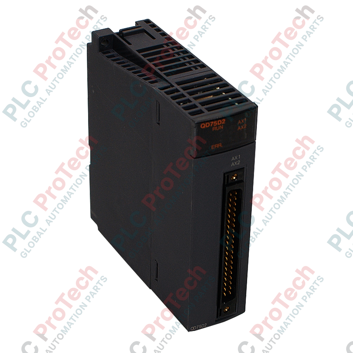
Manufacturer: Mitsubishi Electric
Product No.: QD75D2
Country of origin:United States
Product Type: PLC Positioning Modules
Payment: T/T, Western Union
Weight: 1000g
Shipping port: Xiamen
Warranty: 12 months
For precise multi-axis motion control within the MELSEC Q Series architecture, the Mitsubishi Electric QD75D2 provides high-speed differential driver pulse train outputs for up to two independent axes. This high-performance positioning module enables seamless integration of point-to-point, speed-position, and interpolated path control directly from the PLC backplane to high-resolution servo drives.
| Parameter | Specification Value |
|---|---|
| Manufacturer | Mitsubishi Electric |
| Model Number | QD75D2 |
| Control Axes | 2 axes |
| Output Type | Differential driver (Line driver) |
| Max. Output Pulse Rate | 1 Mpps |
| Max. Connection Distance | 10 meters |
| Interpolation Functions | 2-axis linear interpolation, 2-axis circular interpolation |
| Control Modes | PTP (Point To Point), Path control, Speed control, Speed-position switching, Position-speed switching |
| Positioning Data Points | 600 data points per axis (Nos. 1 to 600) |
| Backup Memory | Flash ROM (Max. 100,000 write cycles) |
| Internal Current Consumption | 0.56 A (at 5V DC) |
| Occupied I/O Points | 32 points (Intelligent function module assignment) |
| External Interface Connectors | A6CON1, A6CON2, A6CON4 (sold separately) |
| Applicable Wire Size | 0.3 mm2 (A6CON1/A6CON4), AWG 24 (A6CON2) |
| Country of Origin | Japan |
| Shipping Weight (Calculated) | 1.00 kg |
The QD75D2 features differential line driver outputs, distinguishing it from the open-collector QD75P2. While the QD75P2 is limited to a 200 kpps output rate and a 2-meter physical cable run, the QD75D2 supports up to 1 Mpps and a 10-meter connection distance. If you are upgrading from a P-series to a D-series module, you must replace the external cabling and verify that the command pulse input of your servo amplifier is configured to receive differential line receiver signals.
When operating in "degree" control mode, ensure that the software configuration accounts for the axis rotation limits. If the axis is set to endless rotation, proper handling of the overflow/underflow boundary is required in the PLC logic to prevent unexpected positioning jumps. Additionally, write operations to the Flash ROM must be managed carefully; do not exceed the 100,000-cycle limit by executing automated writes within cyclic execution blocks.
Always use shielded twisted-pair cabling for the pulse output lines to mitigate electromagnetic interference (EMI). The shield should be grounded at the control panel entry point. When wiring the A6CON1 or A6CON4 connectors, ensure the wire gauge is exactly 0.3 mm2 to guarantee robust physical terminal retention and prevent intermittent signal loss under cabinet vibration.
CRITICAL WARNING:
Before installing, removing, or wiring the QD75D2 module, ensure that the main power supply to the PLC rack and all external power sources for the servo amplifiers are completely de-energized. Failure to do so may result in electric shock, module damage, or unintended machine movement.
Align the module's bottom retaining latch with the slot on the Q-series base unit, then push the module firmly into the backplane connector.
Secure the module to the base unit using the top fixing screw (tighten to the torque specified in the manual, typically 0.36 to 0.48 N·m).
Connect the pre-wired A6CON1, A6CON2, or A6CON4 external connector to the front interface of the module, ensuring the connector lock mechanism is fully engaged.
Power up the PLC rack, verify that the "RUN" LED on the module illuminates, and use GX Works to perform initial parameter configuration and test runs.
Global Express Shipping
Returns & Warranty
Orders are processed and delivered Monday-Friday (excluding public holidays).
For full eligibility, restocking fees, and international return details, please view our official Refund & Return Policy .
| Country of origin |
United States
|

A practical engineering guide to PLC CPU operation, from deterministic scan cycles and I/O image tables to memory, communications, diagnostics, redundancy, processor sizing, and reliable system...

Sostituire un 1756-L73 non significa automaticamente aggiornare il firmware. Questa guida confronta le versioni 19.013, 21.011 e 31.011, concentrandosi sulla compatibilità dei progetti, sulle...

Implementa un circuito luminoso XOR con 3 interruttori SPST in LogixPro o RSLogix 500 utilizzando un bit di relè interno. Include tabelle della verità, equazioni booleane e verifica.

Integra Allen-Bradley CompactLogix, Caterpillar ATS e generatori nel DCS DeltaV tramite Modbus RTU. Include i gateway ProSoft MVI69-MCM e Miille DIN266.

L’istruzione ONS si attiva, ma la bobina OTE non rimane mai eccitata in Studio 5000 perché il one-shot è vero solo per una scansione. Usa OTL/OTU oppure una logica di autoritenuta.

Configura i servoazionamenti Allen-Bradley Kinetix 5500 su EtherNet/IP. Include CIP Sync, la temporizzazione IEEE 1588 V2, la selezione degli switch Stratix, la topologia DLR e l’HMI.