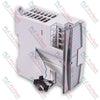
Opis
Zaprojektowany do gęstego pozyskiwania danych w przemysłowych sieciach PLC, moduł wejść analogowych Omron CJ1W-AD041-V1 zapewnia szybką, wielokanałową digitalizację w kompaktowej architekturze serii CJ1. Moduł umożliwia bezpośrednie podłączanie standardowych czujników procesowych, przetworników i przepływomierzy, przekształcając analogowe pomiary fizyczne w bardzo precyzyjne dane cyfrowe. Dzięki solidnej konstrukcji ukierunkowanej na niezawodność przemysłową zapewnia wybieralne poziomy rozdzielczości oraz zintegrowane funkcje przetwarzania sygnału bezpośrednio na poziomie sprzętowym, zmniejszając obciążenie obliczeniowe centralnego procesora.
Funkcje
-
Digitalizacja z dużą szybkością: Wybieralny okres konwersji do zaledwie 250 mikrosekund na punkt umożliwia obsługę dynamicznych pętli sterowania w czasie rzeczywistym.
-
Elastyczne tryby rozdzielczości: Konfigurowalna rozdzielczość wyjścia cyfrowego 1/4000 lub 1/8000, zależnie od wymagań aplikacji dotyczących precyzji.
-
Zintegrowane kondycjonowanie sygnału: Wbudowane przetwarzanie wartości średniej, podtrzymywanie wartości szczytowej i wykrywanie odłączenia czujnika ograniczają potrzebę stosowania złożonej logiki drabinkowej PLC.
-
Odłączana architektura okablowania: Wyposażony w 18-stykową odłączaną listwę zaciskową ze śrubami M3, umożliwiającą szybkie wstępne okablowanie lub wymianę modułu bez zakłócania okablowania obiektowego.
Zastosowania
- Monitorowanie przepływu, poziomu i ciśnienia w instalacjach uzdatniania wody i oczyszczania ścieków.
- Systemy monitorowania temperatury wykorzystujące zewnętrzne przetworniki sygnału.
- Wielosiłownikowe mechaniczne układy sprzężenia zwrotnego położenia i przemieszczenia.
- Systemy śledzenia procesów fabrycznych i kontroli środowiska.
Dane techniczne
| Parametr |
Specyfikacja |
| Producent |
Omron |
| Numer modelu |
CJ1W-AD041-V1 |
| Seria |
Seria CJ (CJ1) |
| Typ modułu |
Moduł wejść analogowych |
| Liczba wejść analogowych |
4 kanały |
| Zakres sygnału wejściowego (napięcie) |
1–5 V, 0–5 V, 0–10 V, -10–10 V |
| Zakres sygnału wejściowego (prąd) |
4–20 mA |
| Maksymalne znamionowe napięcie wejściowe |
Napięcie: +/-15 V, prąd: +/-30 mA |
| Impedancja wejściowa |
Wejście napięciowe: minimum 1 MΩ, wejście prądowe: 250 Ω (wartość znamionowa) |
| Okres konwersji A/C |
1 ms na punkt lub 250 mikrosekund na punkt (konfigurowalne) |
| Rozdzielczość |
1/4000 lub 1/8000 (konfigurowalne) |
| Izolacja |
Transoptor między sygnałami wejścia/wyjścia a sygnałami sterownika (brak izolacji między poszczególnymi kanałami wejściowymi) |
| Zaciski zewnętrzne |
18-stykowa odłączana listwa zaciskowa (śruby M3) |
| Pobór prądu |
maksymalnie 420 mA przy 5 V DC |
| Temperatura pracy |
od 0 do 55°C |
| Wymiary (W x wys. x gł.) |
3,1 cm x 9,0 cm x 6,5 cm |
| Masa transportowa (obliczona) |
2,0 kg |
Empiricalzne informacje inżynieryjne
Modele alternatywne i zgodność
CJ1W-AD041-V1 to zaktualizowana wersja sprzętowa klasycznego modułu CJ1W-AD041. Przy zachowaniu standardowego sposobu montażu fizycznego i przypisania obszarów logicznych wersja V1 wprowadza tryb szybkiej konwersji (250 mikrosekund/punkt), zgodny z nowszymi jednostkami CPU CJ1M, CJ2M i CJ2H. Przy wymianie starszego modułu bez wersji V1 w istniejących systemach należy potwierdzić, że konfiguracja oprogramowania systemu odpowiada profilom szybkości konwersji i rozdzielczości ustawionym w parametrach jednostki PLC.
Pułapki aplikacyjne i uwagi inżynierskie
Należy pamiętać, że moduł zapewnia izolację elektryczną między wejściami a wewnętrzną logiką sterownika, ale nie zapewnia izolacji między poszczególnymi kanałami wejściowymi. Jeśli system obejmuje urządzenia obiektowe znajdujące się na różnych potencjałach uziemienia, wystąpią problemy z pętlami uziemienia, powodujące dryft sygnału lub ostatecznie uszkodzenie sprzętu. Aby temu zapobiec, w przypadku wielopunktowych urządzeń obiektowych w środowiskach o wysokim poziomie zakłóceń lub rozdzielonych uziemieniach zawsze stosuj zewnętrzne izolatory sygnałów między kanałami.
Wskazówki dotyczące uruchamiania i okablowania
W przypadku wejść prądowych (od 4 do 20 mA) przed zasileniem pętli należy zewrzeć zaciski wejścia napięciowego (V IN) i wspólnego (COM) odpowiedniego kanału. Niezastosowanie tej zworki w aktywnych konfiguracjach pętli prądowej może uszkodzić wewnętrzny rezystor 250 omów wskutek wystąpienia napięcia na wejściu o wysokiej impedancji. Zawsze prowadź przewody sygnałów analogowych oddzielnie od linii zasilania prądem przemiennym o wysokim napięciu, aby zapobiec indukowaniu zakłóceń magnetycznych.
Wytyczne dotyczące instalacji
OSTRZEŻENIE KRYTYCZNE
Przed zamontowaniem, demontażem lub podłączeniem tego modułu upewnij się, że cały stojak PLC oraz zasilacze pętli powiązanych urządzeń pomiarowych są całkowicie odłączone od zasilania. Wymiana modułu w aktywnym stojaku może uszkodzić stany pamięci CPU, wywołać systemowe błędy magistrali i doprowadzić do trwałego uszkodzenia sprzętu.
1
Dopasuj dolne wycięcie modułu CJ1W-AD041-V1 do szczeliny w płycie bazowej lub sąsiednim module, a następnie obróć go ku górze i umieść na miejscu.
2
Starannie zablokuj żółte suwaki u góry i u dołu modułu, aby fizycznie połączyć urządzenie z magistralą stojaka.
3
Podłącz listwę zaciskową M3 za pomocą ekranowanych przewodów skręcanych. Uziem ekran tylko z jednej strony (zazwyczaj przy zacisku uziemienia sterownika PLC), aby ograniczyć zakłócenia elektromagnetyczne.
4
Dokładnie sprawdź przełączniki wyboru zakresu na obudowie modułu fizycznego (jeśli występują) i ustaw obszar DM w oprogramowaniu CX-Programmer tak, aby odpowiadał tym ustawieniom.