Overview
The 149986-01 + 149992-01 (149986-01/149992-01) combination constitutes the complete 16-Channel Relay Module assembly for the Bently Nevada 3500 Series Machinery Protection System. This full-height solution consists of the 149986-01 Main Control Module and the 149992-01 Output Termination Module. Designed to provide high-density alarming capabilities, this system allows for 16 independent relay outputs that can be programmed with complex "voting logic" via the 3500 Rack Configuration Software. By utilizing AND/OR logic gates, plant engineers can trigger protective actions based on Alert, Danger, or Not-OK statuses from any monitor channel within the rack. This modular relay system is a critical component for automated machinery shutdown, protecting multi-million dollar assets in power plants, refineries, and offshore platforms from catastrophic mechanical failure.
Technical Configuration
The 3500/33 system is designed for maximum flexibility and reliability in industrial control:
-
Logic Integration: Each of the 16 channels features independent Alarm Drive Logic, capable of processing individual measured variables or combinations of monitor channels.
-
Operational Modes: Relays are organized into four groups of four channels. Each group is switch-selectable for Normally De-energized (ND) or Normally Energized (NE) "Failsafe" operation.
-
Standard Contact Construction: Features epoxy-sealed Single-Pole Double-Throw (SPDT) relays with built-in 250 Vrms arc suppressors to ensure long-term contact integrity.
-
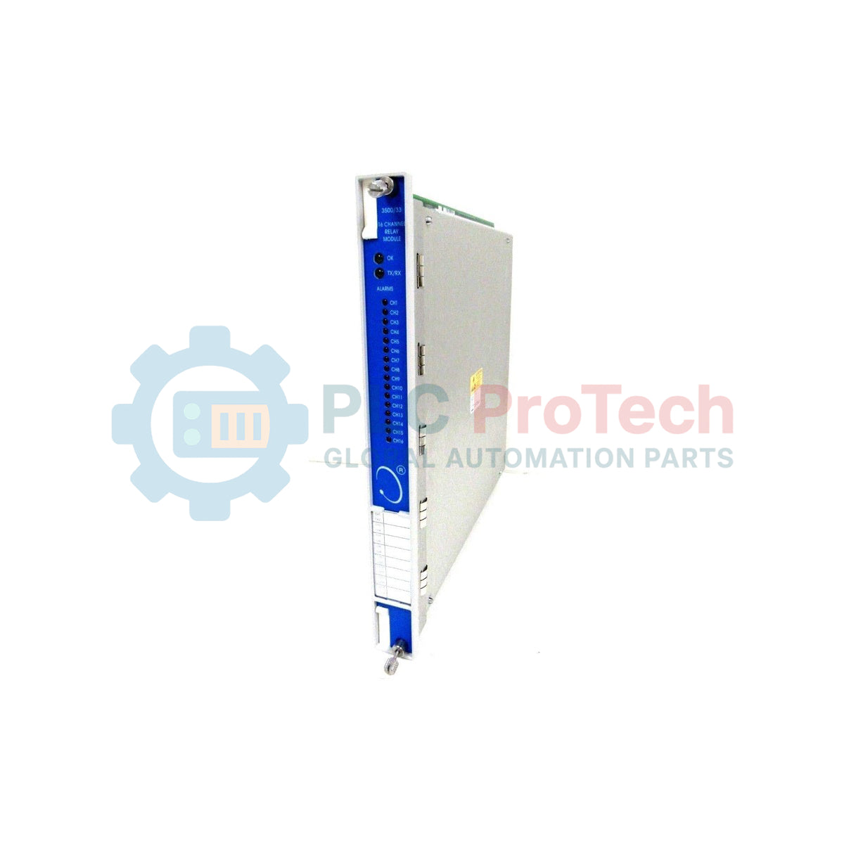
Visual Diagnostics: The front panel includes high-visibility LEDs for module "OK" status, TX/RX communication flashes, and individual Channel Alarm indicators for real-time troubleshooting.
Technical Specifications
| Parameter |
Specification Details |
| Brand |
Bently Nevada |
| Model Number |
149986-01 (Control) + 149992-01 (Output) |
| Series |
3500/33 Machinery Protection System |
| Relay Type |
16-Channel SPDT (Single-Pole Double-Throw) |
| Power Consumption |
5.8 watts typical |
| Max Switched Current |
5 A (Resistive Load) |
| Max Switched Voltage (AC) |
250 Vac |
| Max Switched Voltage (DC) |
125 Vdc (Standard) / 30 Vdc (Failsafe/Haz) |
| Environmental Sealing |
Epoxy-sealed Relays |
| Operating Dimensions |
241 mm x 24.4 mm x 242 mm |
| Main Module Weight |
0.7 kg (1.6 lb) |
Technical FAQs
Can I install the 16-channel relay module in any rack slot?
The 3500/33 can be placed in any of the slots in the 3500 rack, provided they are to the right of the Transient Data Interface (TDI) Module.
What are the software requirements for this specific hardware?
To utilize the 149986-01, your system must run 3500 Rack Configuration Software version 3.3 or later, and Data Acquisition Software version 2.40 or later.
Why is the voltage rating lower for SIL or Hazardous Area systems?
In Failsafe or Multiple Approval (-02) systems, the maximum switched voltage is de-rated to 30 Vdc/Vrms to comply with ATEX and North American Zone 2 spacing requirements and 61010-1 safety type tests.
Engineering & Installation Guide
Contact Load Management
For standard silver contacts used in the 149986-01, the minimum switched load is 100 mA @ 5 Vdc. If your control circuit operates at lower currents (e.g., interfacing with high-impedance digital inputs), ensure you are using the Low Current (gold-plated) variant to prevent contact oxidation and intermittent signaling. For gold-plated contacts, do not exceed 5 mA to avoid damaging the plating.
Arc Suppression and Inductive Loads
While the module includes standard 250 Vrms arc suppressors, we strongly recommend installing external flyback diodes (for DC) or varistors (for AC) when driving high-inductance solenoid valves. This reduces EMI and extends the relay contact life beyond the rated 10,000 cycles.
System Compatibility and Safety
If this module is integrated into a Functional Safety (SIL) loop, you must strictly adhere to the restricted voltage limits specified in the safety certificate. Exceeding 30 Vdc in a hazardous area application violates the equipment's certification and may create a spark hazard. Always verify the "Normally Energized" vs "Normally De-energized" switch positions before powering the rack to prevent accidental machine trips during commissioning.