Architectural Overview & Process Application
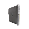
The 8164-4002 (81644002) is a high-density, 32-channel digital output module developed by Alstom under the legacy GEM80 PLC platform. Purpose-built for industrial control applications requiring vast I/O consolidation, this module handles 32 discrete 24 VDC outputs, with each channel rated to drive up to a 0.5 A load. It is widely utilized across heavy industrial plants—such as water treatment facilities, power generation stations, metal processing mills, and marine propulsion systems—to command field-side actuators, indicator lamps, intermediate relays, and solenoid valves. By interfacing directly with the central GEM80 processor backplane, the 8164-4002 (81644002) executes status changes with minimal bus latency. This rapid signal transmission ensures crisp, real-time control execution, optimizes sequence interlocking, and minimizes operational downtime during complex process cycles.
Hardware Infrastructure & Channel Layout
The technical architecture of the 8164-4002 module focuses on density, signal isolation, and quick diagnostic verification.
-
High-Density Point Configuration: Features a compact layout incorporating 32 distinct output pathways divided into manageable, commoned channel groups to maximize physical space efficiency in the PLC rack.
-
Onboard Status Visualization: The front panel contains a dedicated array of LED status indicators corresponding directly to each of the 32 channels, enabling instant visual confirmation of logic states for maintenance personnel.
-
Optocoupler Logic Isolation: Uses robust internal optocouplers to galvanically isolate the delicate GEM80 backplane logic circuits from field-side electrical surges, transients, and switching spikes.
Physical & Electrical Performance Indexes
| Technical Parameter |
Engineering Specification |
| Model Number |
8164-4002 |
| Brand / Series |
Alstom / GEM80 Series |
| Module Classification |
High-Density Digital Output Module |
| Channel Count |
32 Channels |
| Nominal Operating Voltage |
24 VDC |
| Maximum Current Per Channel |
0.5 A |
| Total Module Load Capacity |
Subject to group common limitations |
| Signal Galvanic Isolation |
Integrated (Optocoupled) |
| Front Panel Diagnostics |
Channel status LEDs |
| Physical Dimensions |
23.5 x 23.5 x 2.4 cm |
| Net Equipment Weight |
0.42 kg |
| Operating Temperature |
0 to 55 deg C |
| Storage Temperature Limits |
-20 to 70 deg C |
Technical FAQs
How do you locate the specific channel failure when a field device fails to pick up?
Begin by checking the front panel LED indicator array on the 8164-4002 module. If the corresponding channel LED illuminates but the field actuator remains unenergized, use a multimeter to measure the 24 VDC voltage output directly at the terminal strip connector. If voltage is present at the module terminal, the issue resides in the field wiring or the actuator coil itself; if no voltage is present, the internal driving transistor for that specific point may be damaged.
What are the primary precautions when connecting highly inductive loads like large relay coils to this module?
Each channel is strictly rated for 0.5 A. When driving inductive loads, the collapsing magnetic field can produce a reverse high-voltage transient (inductive kickback) capable of punching through the output transistors. To safeguard the module circuits, you must wire an external flyback diode (such as a 1N4007) in reverse parallel across the inductive load terminal points.
Since the Alstom GEM80 series is discontinued, what is the best strategy for handling hardware failures?
As original factory manufacturing has ceased, direct repair lines are closed. Plant management should source certified Original New legacy inventory or fully tested remanufactured spares. To prevent an extended line stoppage, keep identical, verified replacement cards in an onsite, climate-controlled storage locker for immediate hotswap deployment.
Field Engineering & Installation Protocol
-
Backplane Isolation and Insertion Rules:
Never insert or extract the 8164-4002 module while the GEM80 chassis power supply is switched on. Swapping modules with live backplanes induces transient voltage arcs across the data bus connector pins, which can disrupt adjacent running processors and destroy the CMOS memory logic of the output board.
-
Group Common Power Distribution:
The 32 channels are grouped into commoned electrical banks. Ensure that your external 24 VDC field power supply wiring matches the specific group terminal assignments. Use appropriately sized copper conductors (minimum 18 AWG) for the common feed lines to accommodate the cumulative current load if all 32 channels are activated simultaneously.
-
Enclosure Thermal Management:
When multiple high-density output modules are deployed in a single GEM80 rack panel, the combined power dissipation from the 0.5 A channel switches can generate significant heat. Maintain a minimum vertical spacing of 75 mm above and below the chassis for proper air convection. If the temperature inside the enclosure climbs past 45 deg C, integrate an active fan cooling system to preserve component longevity.