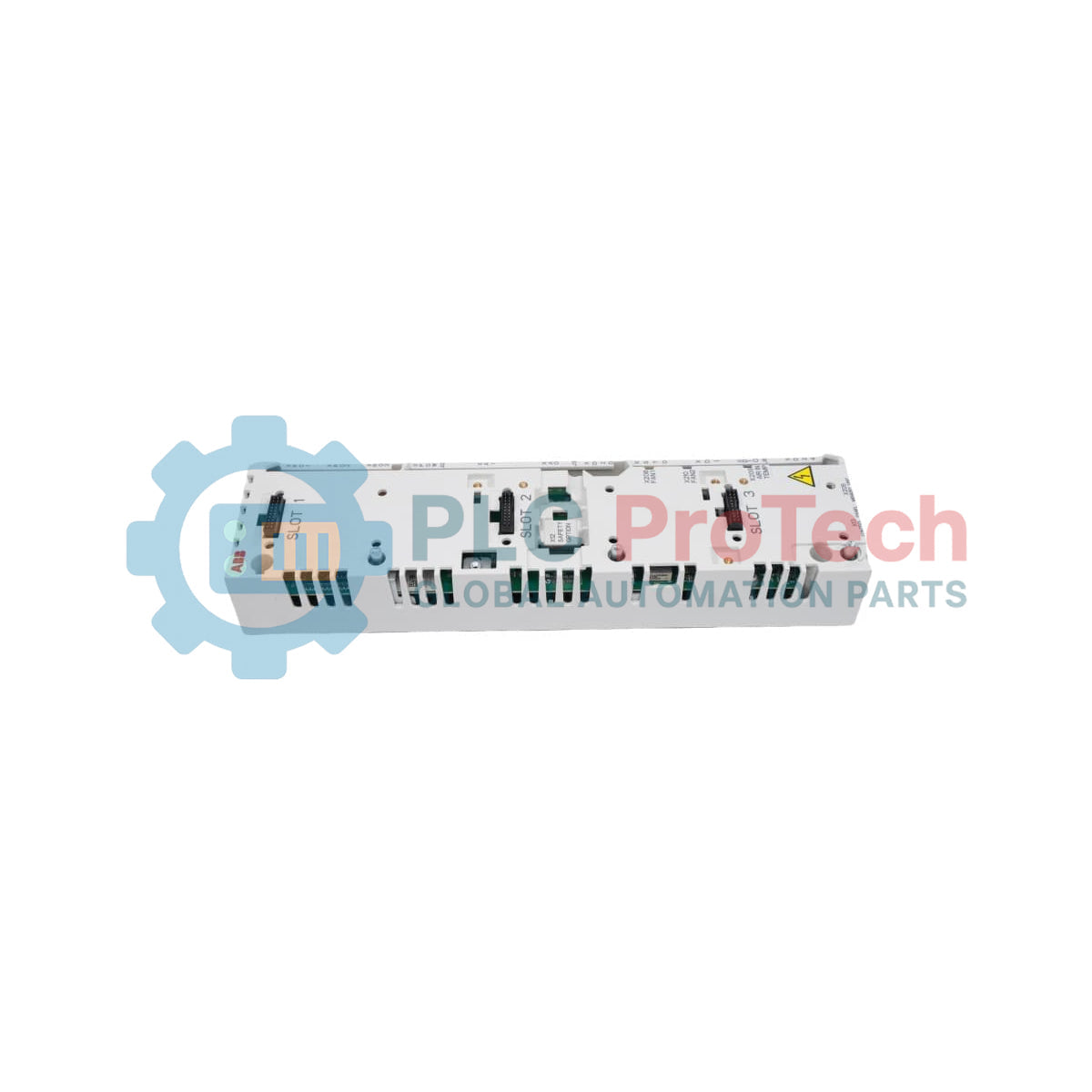
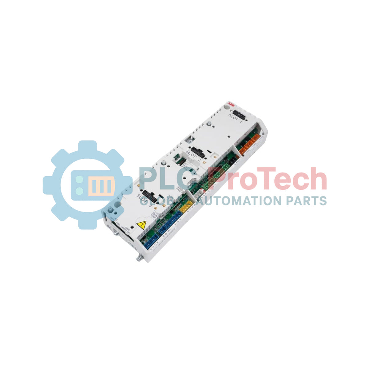
The ABB 3AXD50000005164, also cataloged as the ZCU-14 Control Unit, operates as a dedicated hardware component for internal control execution within ABB drive system assemblies. ABB classifies the unit as a main assembly spare part associated with drive control hardware. Manufacturer documentation specifies replacement ordering through material code 3AXD50000182992.
Suffix Breakdown & Model Matrix
ABB documentation does not provide an official suffix matrix or configurable option breakdown for 3AXD50000005164. The following identifiers are explicitly listed by the manufacturer:
| IdentifierDescription |
|
| 3AXD50000005164 |
ZCU-14 Control Unit |
| 3AXD50000182992 |
Replacement packed spare control unit |
Hardware Specifications
| ParameterSpecification |
|
| Model |
3AXD50000005164 |
| ABB Type Designation |
ZCU-14 |
| Catalog Description |
ZCU-14; CONTROL UNIT |
| Product Name |
CONTROL UNIT |
| Brand |
ABB |
| Product Type |
Spare Parts |
| Technical Information |
Main Assembly |
| Origin |
China / Romania |
| Net Weight |
0.8 kg |
| Gross Weight |
0.8 kg |
| Dimensions |
310 mm x 95 mm x 55 mm |
| Gross Volume |
1.62 dm3 |
| Package Quantity |
1 piece |
| Customs Tariff Number |
85049090 |
| CN8 |
85049099 |
| Operating Temp |
Not specified by manufacturer |
| Power Consumption |
Not specified by manufacturer |
| Frame Size |
Spare_Parts |
| WEEE Category |
Product Not in WEEE Scope |
Drive Control Assembly Integration
ABB identifies the ZCU-14 as a control unit main assembly used within drive spare part structures. The manufacturer documentation does not publish standalone electrical ratings, fieldbus specifications, or external I/O characteristics for this component.
The unit is supplied as an internal drive control assembly rather than a field-mounted automation module. Replacement activity should therefore follow the associated ABB drive service documentation and hardware compatibility references.
ABB additionally notes that lithium battery classifications UN3181/3090/3091 may affect transportation handling and shipping timelines for this assembly.
Frequently Asked Questions
Q: Does ABB publish standalone operating voltage specifications for the ZCU-14?
A: The provided manufacturer documentation does not include standalone electrical input ratings or operating voltage data for this control unit.
Q: Can 3AXD50000005164 be ordered directly as an active spare part?
A: ABB documentation states that material code 3AXD50000182992 should be ordered instead of 3AXD50000005164.
Q: Does the manufacturer provide field wiring or terminal allocation data for the module?
A: No external terminal, field wiring, or channel allocation information is listed in the provided ABB documentation.
Field Installation Guidelines
Verify the installed drive assembly and associated spare part compatibility before replacement. Because the unit is identified as a main assembly control component, installation should be performed only after complete isolation of cabinet control power and drive power sources.
Use electrostatic discharge protection during handling and avoid direct contact with connector surfaces or exposed circuit sections. Confirm connector alignment before seating the assembly into the host hardware structure.
Control assemblies removed from service should be stored inside anti-static packaging and protected from conductive contamination, condensation, and vibration during transport or storage.The B&R X20SC2212 is a safety-oriented digital mixed I/O module belonging to the X20 System series, engineered to handle fail-safe digital signals within critical industrial automation architectures. The electronic component integrates 6 safe type A digital inputs alongside 6 complementary pulse outputs operating on a 24 VDC nominal voltage framework, combined with 2 safe type B1 digital outputs rated at 0.5 A per channel. Utilizing an Output Signal Switching Device (OSSD) monitoring architecture with a response diagnostic cycle of under 500 µs, the module actively executes control logic to detect cross-faults, short circuits, and ground leakage across internal channels. Integrated safety mechanisms, including reverse polarity protection on the input circuitry, ensure predictable behavior under fluctuating operational voltage bands ranging from -15% to +20% of nominal parameters.
Hardware Specifications
| Parameter |
Specification |
| Manufacturer |
B&R (Bernecker + Rainer) |
| Model / Type |
X20SC2212 |
| Product Family |
X20 System |
| Module Category |
Safe digital mixed module |
| Safe Digital Inputs |
6 type A safe inputs |
| Pulse Outputs |
6 test pulse outputs |
| Safe Digital Outputs |
2 type B1 safe outputs |
| Maximum Continuous Output Current |
0.5 A per channel |
| OSSD Switching Cycle |
< 500 µs |
| Nominal Supply Voltage |
24 VDC |
| Permissible Supply Voltage Range |
20.4 – 28.8 VDC (24 VDC -15% / +20%) |
| Integrated Circuit Protection |
Reverse polarity protection |
| Operational Humidity Range |
5 – 95% (Non-condensing) |
| Storage Humidity Range |
5 – 95% (Non-condensing) |
| Transport Humidity Range |
5 – 95% (Non-condensing) |
| Protection Class |
IP20 |
| Ambient Operating Temperature |
0 – 55 °C |
| Shipping Weight |
2 kg |
Engineering Notes
-
Backplane Communication Integrity: The module depends entirely on the cyclic data exchange protocol of the X20 backplane. Rack compatibility must be verified with the corresponding X20 bus base to ensure functional matching of internal power rails.
-
OSSD Filtering Mechanisms: The integrated diagnostic system evaluates the OSSD pulse intervals to intercept transient voltage drops; peripheral field actuators must tolerate test pulses of < 500 µs without triggering unintended dropouts or contact chatter.
-
Fail-Safe Input Configurations: Type A inputs are structured to monitor dual-channel redundant configurations; corresponding functional safety software must validate the input state consistency within the defined synchronism time window.
Field Guidelines
-
Shield Grounding and Cable Routing: Ensure all safety-critical signal lines are routed using twisted-pair shielded cabling. Ground the cable shield directly at the entry point of the electrical enclosure using a low-impedance grounding rail to suppress high-frequency electromagnetic noise.
-
EMC Isolation Distances: Maintain a physical separation of at least 200 mm between the X20SC2212 low-voltage sensor lines and any high-power AC lines or variable frequency drive (VFD) output cables running inside parallel cable ducts.
-
Terminal Insulation and Strain Relief: Implement a mechanical strain relief layout to enforce a permanent cable bend radius of no less than 10 times the cable diameter before the conductors enter the front terminal block cage clamps.
Technical & Procurement FAQ
Question: Does the part number X20SC2212 include the required bus base and terminal block accessories?
Answer: The part number covers the core electronic module assembly only. The corresponding X20 bus base and front plug-in terminal blocks must be sourced as separate mechanical line items to complete the physical installation.
Question: Is the X20SC2212 module hot-swappable within an active X20 system rack?
Answer: The three-part modular topology of the B&R X20 system allows the active electronic block to be replaced during live operations without disrupting the backplane communication loop or terminal block wiring of adjacent hardware segments.
Question: What firmware matching parameters must be met when retrofitting an existing safety rack with this component?
Answer: Hardware revisions and functional checksum safety configurations must be parsed via the Automation Studio engineering software to guarantee system compatibility and clear the watchdog parameters prior to resuming safe cyclic data exchange.