Product Overview
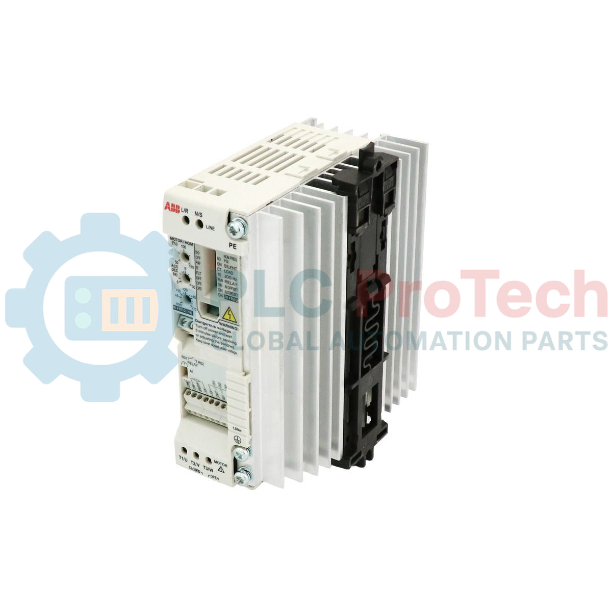
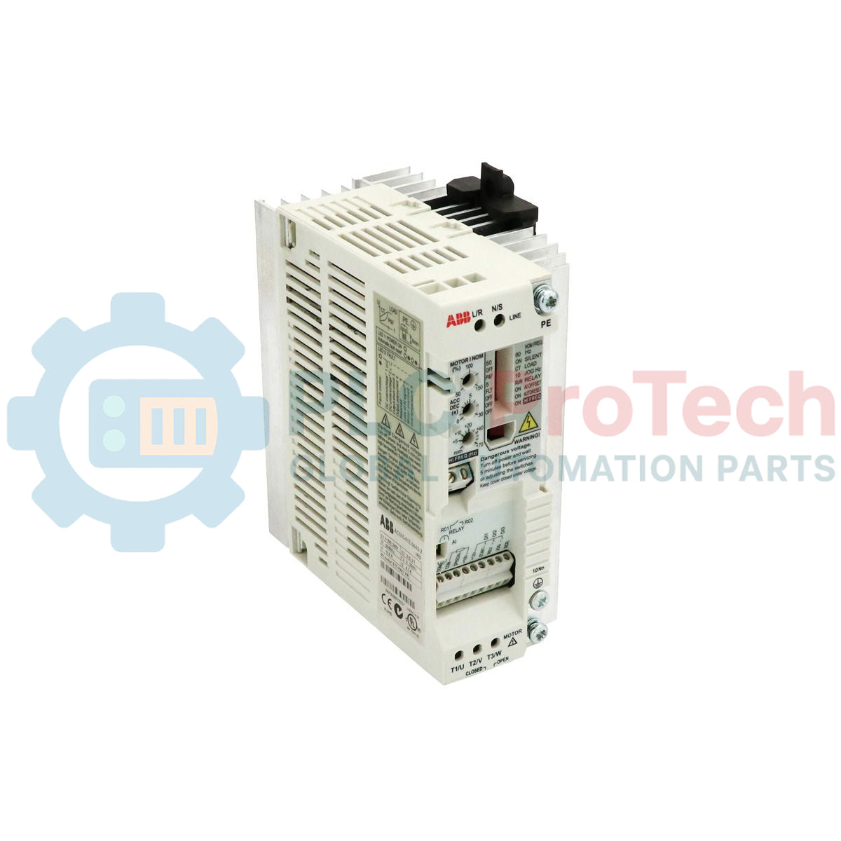
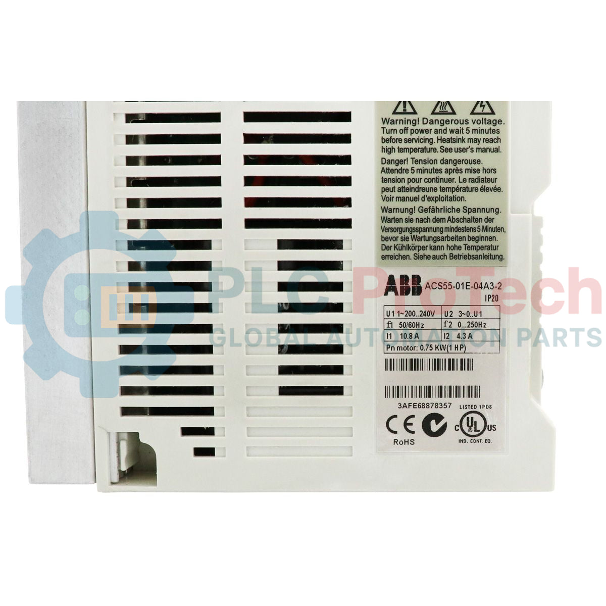
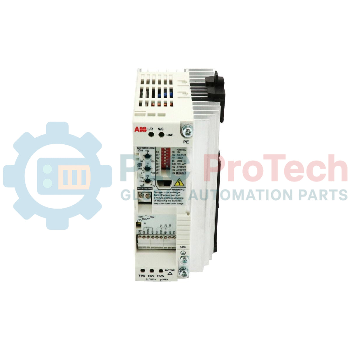
ACS55-01E-04A3-2 is a compact micro AC drive from the ABB ACS55 series designed for small motor speed control applications requiring single-phase power input and three-phase motor output. The drive operates on 200-240 VAC input voltage and provides 0.75 kW rated motor power with 4.3 A continuous output current.
This drive is commonly installed in compact conveyor systems, small pumps, workshop automation equipment, HVAC auxiliary systems, fans, gate control systems, and light-duty industrial machinery where cabinet space is limited. The integrated EMC filter and DIN rail mounting structure simplify installation inside standard electrical enclosures used in OEM machinery and building automation systems.
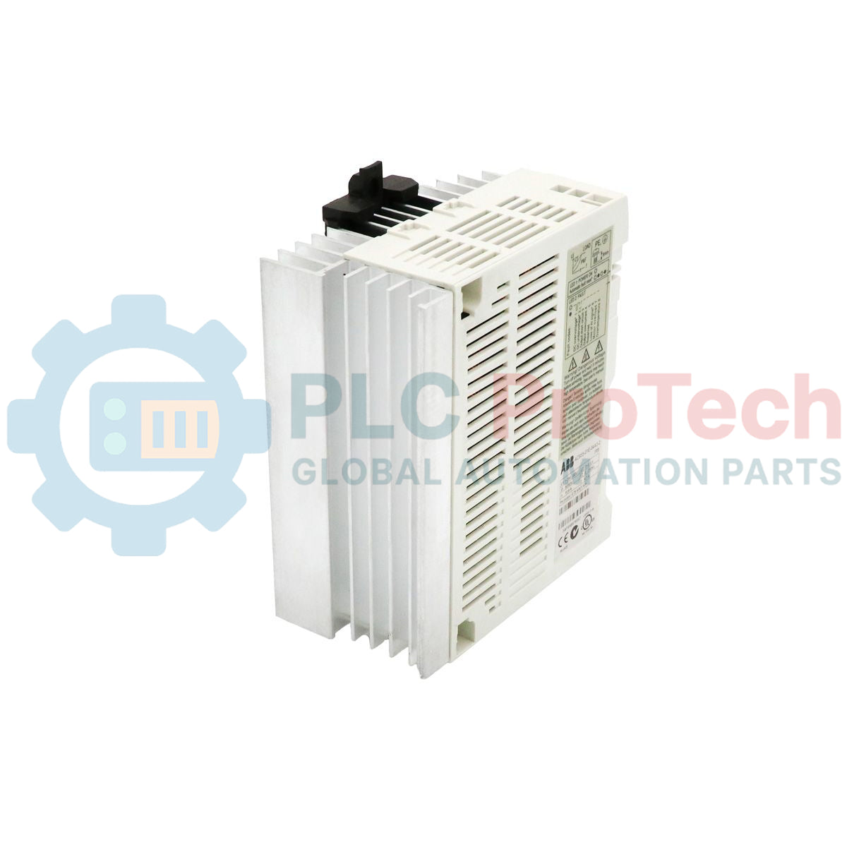
The ACS55 series supports stable motor acceleration and deceleration while reducing mechanical stress during startup operation. Its compact Frame B construction allows flexible wall or DIN rail installation in industrial control cabinets.
Technical Configuration
The ACS55-01E-04A3-2 integrates motor control, EMC protection, and overload monitoring within a compact micro drive architecture.
| Feature |
Description |
| Drive Series |
ACS55 |
| Input Supply |
Single-phase 200-240 VAC |
| Output Supply |
Three-phase motor output |
| Frame Size |
B |
| Mounting Method |
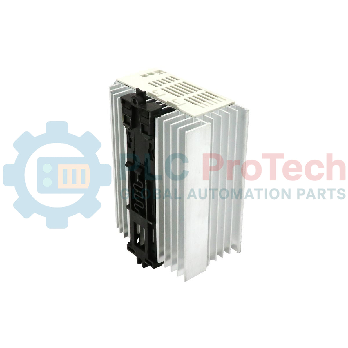
DIN rail or wall mounting |
| EMC Filter |
Built-in |
| Cooling Method |
Air-cooled |
| Protection Functions |
Overvoltage, overload, short-circuit, motor overload |
| Enclosure Rating |
IP20 |
The drive supports switching frequencies up to 16 kHz depending on application and thermal conditions.
Technical Specifications
| Parameter |
Value |
| Model |
ACS55-01E-04A3-2 |
| Brand |
ABB |
| Product Type |
Micro AC Drive |
| Series |
ACS55 |
| Rated Power |
0.75 kW |
| Horsepower |
1 hp |
| Input Voltage |
200-240 VAC |
| Input Phase |
Single-phase |
| Output Voltage |
0-U1 |
| Output Phase |
Three-phase |
| Continuous Output Current |
4.3 A |
| Maximum Output Current |
6.5 A |
| Input Current |
10.8 A |
| Switching Frequency |
5 kHz standard, up to 16 kHz |
| Power Loss |
51 W |
| Protection Rating |
IP20 |
| Mounting Type |
DIN rail or wall mounting |
| Frame Size |
B |
| Operating Temperature |
-20 to +40 deg C |
| Maximum Ambient Temperature |
+50 deg C with derating |
| Width |
72 mm |
| Height |
128 mm |
| Total Height |
170 mm |
| Depth |
156 mm |
| Maximum Cable Size |
2.5 mm2 |
Engineering Notes & Installation Guide
EMC and Shielding:The ACS55-01E-04A3-2 features an internal EMC filter. To maintain compliance with CE directives, motor cables must be shielded. The shield should be grounded 360 degrees at both the drive end and the motor terminal box. Avoid running control cables (Analog/Digital I/O) parallel to the motor power cables to prevent inductive coupling and signal interference.
Thermal Management and Cooling:While the ACS55 is designed for compact spaces, the unit dissipates approximately 51 W of heat at full load. Ensure a minimum clearance of 25 mm on either side of the drive when multiple units are mounted side-by-side. If the ambient temperature exceeds 40°C, the output current must be derated by 1% for every 1°C increase up to 50°C.
Fusing and Circuit Protection:Input protection is mandatory to safeguard the drive against line transients. For IEC installations, use 16 A gG class fuses. For UL-compliant installations, use 20 A Class CC or T fuses. Do not use a contactor on the output side of the drive for motor starting or stopping; use the drive's integrated control logic instead.
Wiring Separation:Maintain a minimum distance of 200 mm between control wiring and power wiring. If the cables must cross, they should do so at a 90-degree angle. Ensure the maximum cable cross-section does not exceed 2.5 mm² to fit the terminal blocks.
Troubleshooting & Hardware FAQ
Q: What is indicated by the LED status on the front panel?A: A green LED indicates power is active and the drive is operational. A red LED indicates a fault condition. Common faults include overcurrent (usually caused by a short circuit or mechanical jam) or undervoltage.
Q: How do I resolve an "Analog Input Loss" fault?A: Verify the integrity of the 0-10V or 4-20mA signal source. Ensure that the DIP switch associated with the analog input type is correctly positioned and that the ground reference for the signal is common with the drive's control terminals.
Q: Can this drive be used with a 1-phase motor?A: No. The ACS55-01E-04A3-2 accepts a 1-phase input but is designed exclusively to drive 3-phase asynchronous induction motors. Attempting to connect a 1-phase motor will result in a phase loss or overcurrent trip.
Q: How is the switching frequency adjusted?A: The switching frequency is set via the internal parameters or DIP switches. While higher frequencies (up to 16 kHz) reduce acoustic motor noise, they increase drive thermal losses and may require further output current derating.