Product Overview
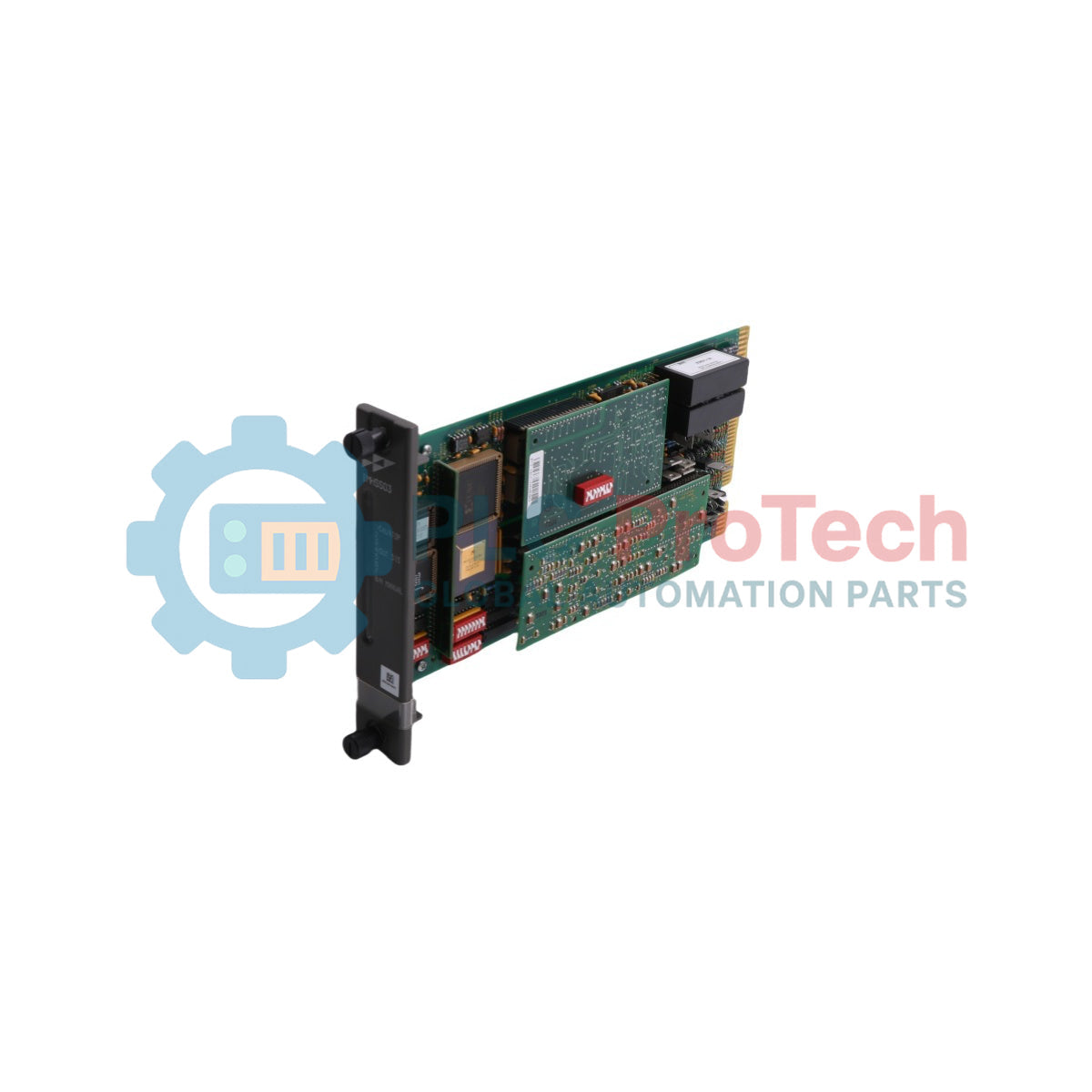
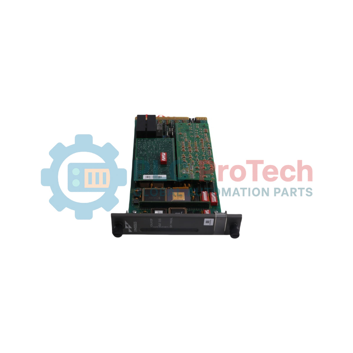
The IMHSS03 (IMHSS03) is a high-precision, microprocessor-driven valve position control module designed for the ABB Bailey INFI 90 and Harmony Rack ecosystems. Engineered for ultra-critical turbine governing loops within power generation plants, petro-chemical refineries, and heavy industrial mechanical drives, this module acts as the definitive hardware link between a multi-function processor (such as the IMMFP01/02/03) and electro-hydraulic servo valves or current-to-hydraulic (I/H) converters. By regulating the precise current outputs sent to the servo mechanisms and reading localized dual-redundant Linear Variable Differential Transformer (LVDT) feedback loops, the IMHSS03 ensures instant, deterministic throttle valve control. Deploying this module eliminates governor valve hunting, mitigates the risk of catastrophic turbine overspeed trips, and drastically lowers un-scheduled station downtime during sudden grid load rejections.
Hardware Architecture and Loop Configuration
The control layout of the IMHSS03 introduces high-performance, redundant processing capabilities designed to maintain continuous control loops under active field component degradation.
-
Demodulator Autotuning Logic: The card contains specialized internal algorithms that automatically tune the demodulator gain circuit matching the specific LVDT transformer parameters. This self-calibration removes manual potentiometer variance and mitigates thermal secondary voltage drift.
-
Actuator Output Layouts: Supports multiple operational methods for the servo valves. Field engineers can set the card to run two active controlling servo valves simultaneously (dual parallel drive) or configure a single active master valve alongside an automated hot-standby secondary valve.
-
Galvanic and Optical Barrier Segregation: The module features enhanced analog-to-digital (A/D) and digital-to-analog (D/A) converters isolated up to full industrial grading. This architecture isolates the INFI 90 backplane from external field ground loops, high-voltage switching surges, and electromagnetic interference (EMI) originating from the turbine deck.
Comprehensive Technical Specifications
Environmental Characteristics
| Environmental Property |
Operational Specifications |
| Ambient Operating Temperature |
0 to 60 deg C |
| Storage and Transport Temperature |
-40 to 75 deg C |
| Relative Humidity Span |
5 to 95% (Non-condensing) |
| Air Quality Demands |
Clean, dry, non-conductive, non-corrosive industrial air |
| Cooling Topology |
Natural convection through modular mounting unit (MMU) slots |
Power Consumption Demands
| Power Supply Rail |
Current Loading Values |
Total Power Dissipation |
| +5 VDC Rail |
240 mA typical |
1.2 W |
| +15 VDC Rail |
12.3 mA typical |
185 mW |
| -15 VDC Rail |
12.3 mA typical |
185 mW |
Analog Input Performance (LVDT Interfaces)
| Input Property |
Engineering Metrics and Limits |
| Number of LVDT Channels |
2 channels (Fully redundant interface blocks) |
| LVDT Configurations |
Supports 3-wire, 4-wire, or 5-wire AC or DC LVDT types |
| A-to-D Resolution Matrix |
24 bits maximum resolution |
| Input Voltage Limits |
0 to 10 VDC, or up to 7.5 VRMS AC |
| LVDT Excitation Frequency |
1.0 kHz to 10.0 kHz (Software selectable options) |
| Excitation Output Current |
50 mA maximum per channel drive |
Analog Output Performance (Servo Drive Outputs)
| Output Property |
Engineering Metrics and Limits |
| Number of Servo Channels |
2 channels (Configurable for simultaneous or standby modes) |
| D-to-A Resolution Matrix |
16 bits resolution |
| Output Current Configurations |
Plus or minus 10 mA, plus or minus 20 mA, plus or minus 40 mA, plus or minus 50 mA, or plus or minus 100 mA |
| Maximum Load Impedance |
Up to 1000 Ohms at full 20 mA output span |
| Loop Isolation Rating |
500 VDC continuous isolation from internal logic blocks |
Digital Input / Output Technical Data
| I/O Property |
Configuration Values |
| Digital Inputs (DI) |
3 isolated input channels (For turbine trip, manual takeover, or interlocks) |
| DI Input Voltage Span |
24 VDC nominal (Internal or external loop wetting) |
| Digital Outputs (DO) |
4 isolated solid-state or relay driver output channels |
| DO Current Sinking Rating |
250 mA maximum per output channel line |
Engineering FAQs
How do you configure the different output current ranges on the IMHSS03?
The choice of servo drive current (e.g., plus/minus 10 mA up to 100 mA) is controlled by a combination of physical hardware onboard dipswitches located on the printed circuit board assembly and the Function Code 150 block parameters inside the Multi-Function Processor configuration. These settings must match the exact specifications on the servo valve nameplate before powering up the system.
Can the IMHSS03 handle older 3-wire LVDT feedback sensors?
Yes. The module is fully programmable to interface with 3-wire, 4-wire, or 5-wire LVDT sensors. The exact sensor type and wiring configuration are specified via termination unit jumper positions and the system block code variables.
What does a flashing amber/red combination on the status LEDs indicate?
The card features 9 diagnostic LEDs. A flashing combination indicates a runtime process exception. This typically means an LVDT feedback wire breakdown, an open-circuit fault on the servo current loop, or that the valve position error has exceeded the pre-programmed tracking deviation deadband for longer than the safe timeout limit.
Field Engineering and Installation Manual
-
Termination Unit Dipshunt and Jumper Alignments: Prior to inserting the module card into the slot, you must set the physical dipshunts and jumpers on the NTMP01 or NKTU01 termination units according to your specific LVDT type (AC or DC excitation). Incorrect jumper alignment can apply damaging DC voltages across an AC LVDT coil, causing permanent sensor failure.
-
Shield Matrix and Grounding Protocol: All field wiring leading to the servo valves and LVDT sensors must utilize independent twisted, shielded pair cables. Ground the shield braid exclusively at the termination unit side of the cabinet ground copper bus bar. Never connect the shield to earth at the turbine valve body, as the high ground potentials on the turbine deck will drive massive ground loop currents through the instrumentation lines, corrupting the 24-bit resolution signals.
-
Function Code 150 Automated Calibration Procedure: Lock out the primary hydraulic header pressure and manually verify that the turbine valves can stroke freely from 0% to 100% without mechanical binding. Execute the automated calibration command via Function Code 150 through your engineering terminal. The processor will map the stroke limits and write the newly derived demodulator gain factors directly into the non-volatile EEPROM memory of the module.
-
Module Mechanical Retention and Seating: Align the board edges with the non-conductive card guides of the single-slot MMU housing. Slide the module in firmly until you feel the rear DIN connectors mate with the backplane. Tighten the top and bottom captive faceplate thumbscrews to 0.4 Nm (3.5 in-lbs) to ensure the card remains properly seated and grounded despite local industrial floor vibrations.