Description
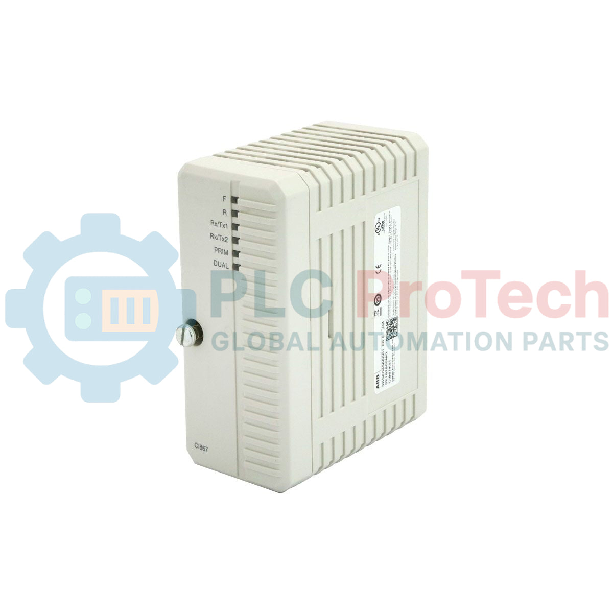
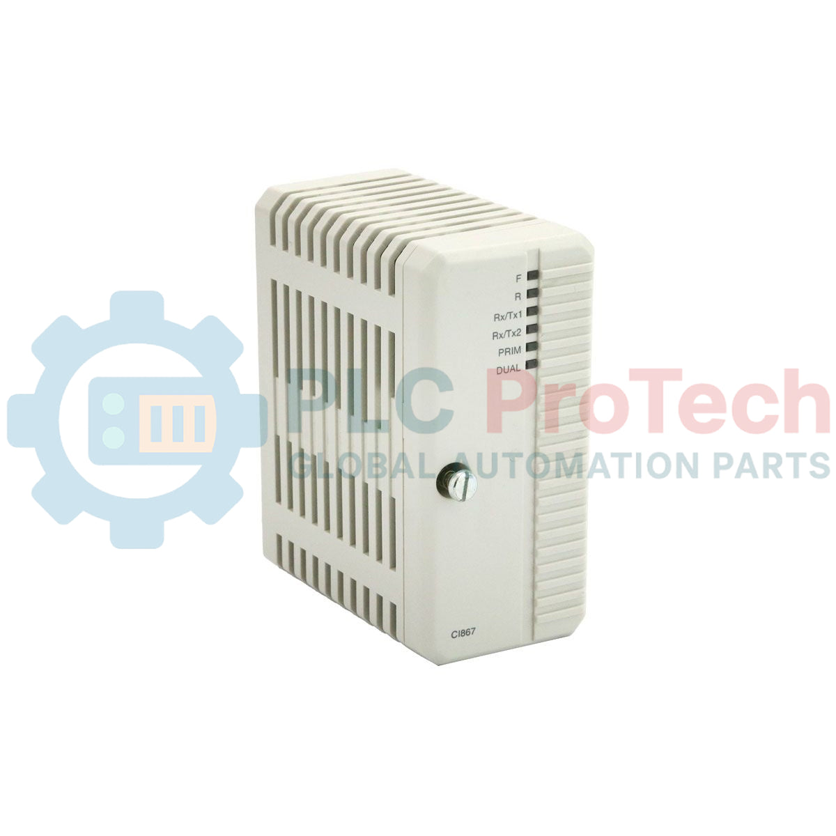
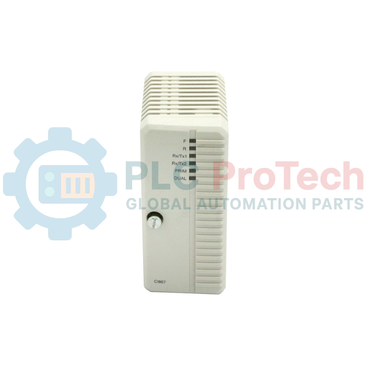
Facilitating seamless Ethernet-based industrial communications, the ABB CI867K01 3BSE043660R1 acts as a high-performance Modbus TCP interface kit within the System 800xA and AC 800M controller architecture. This communication package includes the CI867 communication module and the TP867 baseplate, enabling direct connectivity to field instruments, third-party PLCs, and SCADA control networks. Engineered for high-speed industrial telemetry, it functions natively as both a Modbus TCP Master and Slave, ensuring flexible and reliable data exchanges across modern automated systems.
Key Features
- Dual-channel RJ45 Ethernet interfaces supporting 10/100 Mbps transmission speeds.
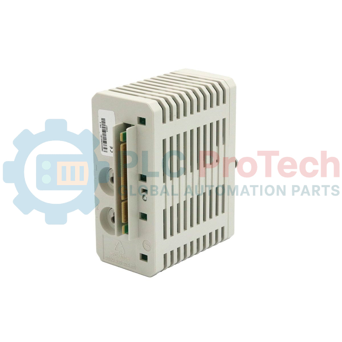
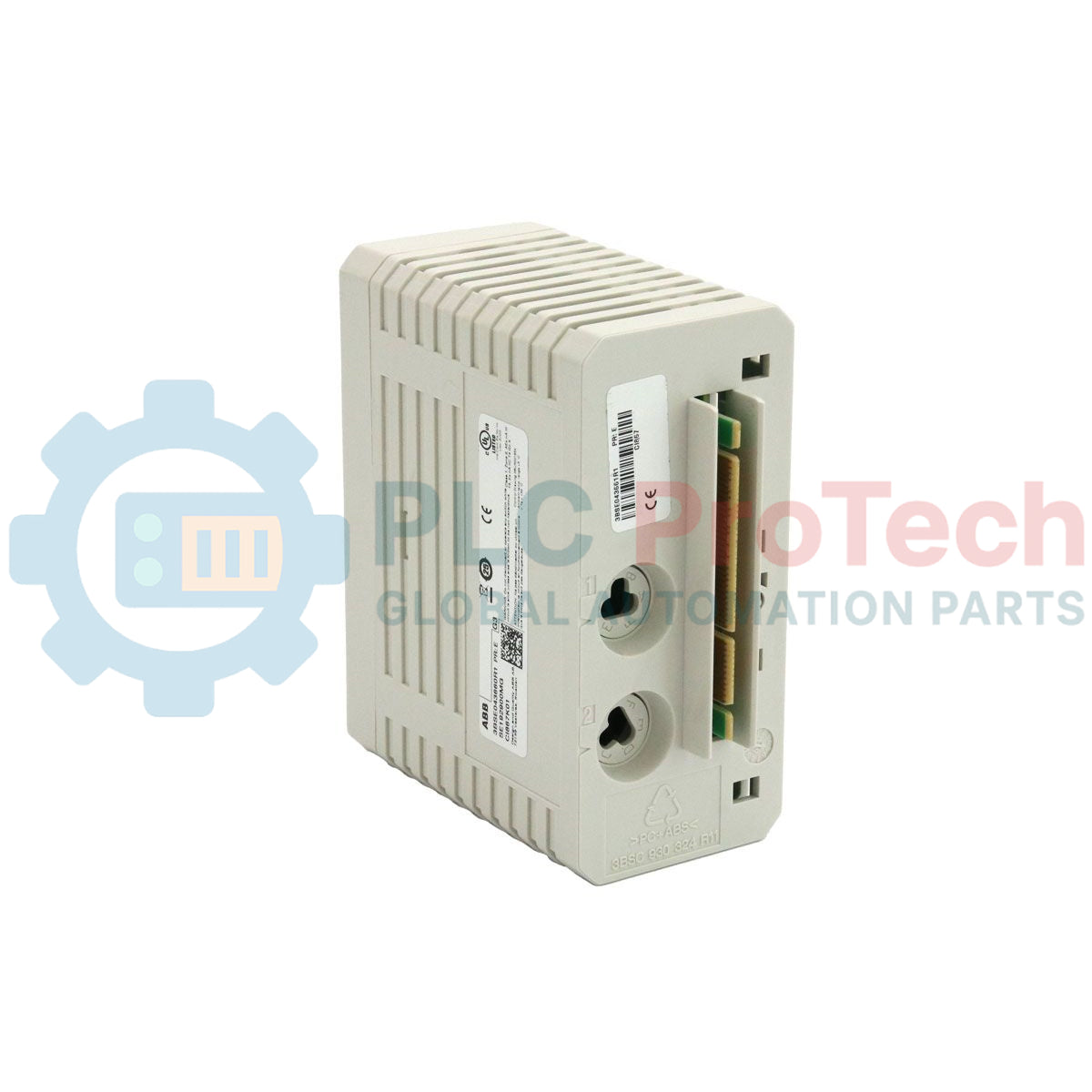
- Includes the rugged TP867 baseplate for stable backplane mounting and reliable shielding.
- Comprehensive protocol handling for Modbus TCP Master and Slave configurations.
- Full integration with ABB Control Builder M configuration software.
- Hot-swappable communication hardware for maximum system availability and reduced downtime.
Industrial Applications
- Integration of intelligent electronic devices (IEDs) and power meters into central control networks.
- Inter-controller communications between ABB AC 800M assemblies and third-party PLC architectures.
- Distributed SCADA telemetry in water treatment, chemical processing, and power generation plants.
Technical Specifications
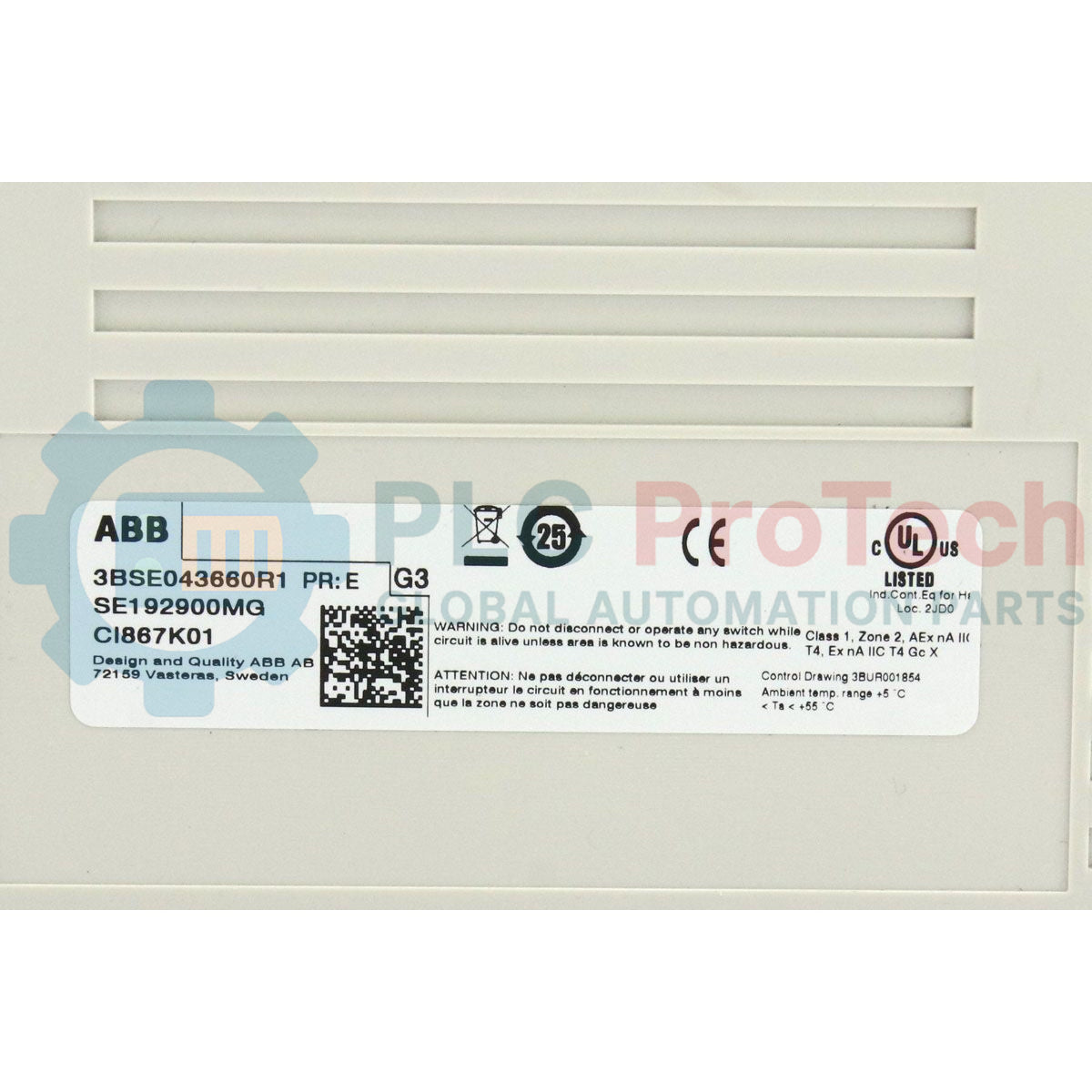
| Manufacturer |
ABB |
| Model Number |
CI867K01 |
| Product ID / SKU |
3BSE043660R1 |
| Module Type |
Modbus TCP Communication Interface |
| Physical Composition |
CI867 Module & TP867 Baseplate Assembly |
| Ethernet Ports |
2x RJ45 (Ch1, Ch2) |
| Transmission Rate |
10/100 Mbps (Auto-negotiation) |
| Connection Limit |
Up to 120 simultaneous TCP connections |
| Customs Tariff Number |
85176200 |
| Country of Origin |
Sweden |
| Net Weight |
0.7 kg |
| Shipping Weight (Calculated) |
0.95 kg |
| Dimensions (D x H x W) |
127.5 x 186 x 59 mm |
Connections and Interfaces
| Interface Terminal |
Interface Type |
Functional Assignment |
| Ch1 |
RJ45 Connector |
Primary Ethernet Connection (Modbus TCP Network) |
| Ch2 |
RJ45 Connector |
Secondary Ethernet Connection / Network Redundancy Path |
| Backplane Connector |
TP867 Baseplate Interconnect |
24 V DC Power Input and Internal System Bus Communication |
Empirical Engineering Insights
Alternative Models & Compatibility
The CI867K01 package directly succeeds older Modbus solutions within System 800xA. It requires Control IT firmware version 5.1 or higher loaded onto the PM8xx controller for correct interface addressing. If you are retrofitting older systems using Control Software version 5.0 or earlier, firmware upgrades or compatibility configuration patches are mandatory to ensure that the AC 800M controller recognizes the dual-channel capability of the TP867 baseplate assembly.
Application Pitfalls & Engineering Notes
To prevent communication module lockups, avoid overloading the 120-connection threshold. When configuring master devices, group individual Modbus polling requests into unified, block-read transactions instead of continuous, discrete register queries. This minimizes packet rates and protects the module's microprocessor from thermal overhead inside enclosed unventilated panels.
Commissioning & Wiring Tips
Always use Shielded Twisted Pair (STP) Cat5e or Cat6 cabling to prevent Electromagnetic Interference (EMI) in high-voltage switchgear environments. Ground the cable shields strictly at the industrial patch panel end rather than the TP867 baseplate to suppress potential ground loops. Confirm that the default network routing tables in Control Builder match the physical local network gateway to bypass ARP resolution failure.
Installation Guidelines
CRITICAL WARNING:
De-energize all AC 800M backplane power lines and external communication devices prior to installing or removing the TP867 baseplate. Static discharge and raw voltage spikes can cause irreversible hardware damage to the communication bus components.
1
Mount the TP867 baseplate onto the grounded standard horizontal DIN rail until the plastic locking tab clicks firmly into place.
2
Align the slide connectors of the adjacent communication or CPU modules to bridge the backplane connection path.
3
Carefully insert the CI867 interface module into the slot of the TP867 baseplate, exerting even pressure until it sits flush.
4
Connect the shielded RJ45 cables to Port Ch1 and/or Ch2, route the cabling through the designated panel ducting, and power on the system for commissioning.