


Diagnosing DeltaV SE5009 Power Problems Before Replacement
A field checklist for separating 24 VDC input, carrier bus, output derating and alarm-contact faults before replacing an Emerson SE5009.
Manufacturer: ABB
Product No.: 3BSE020510R1
Country of origin:Sweden
Product Type: Digital Output Module
Barcode: 85389091
Payment: T/T, Western Union
Weight: 240g
Dimensions: 86.1 mm x 102.0 mm x 58.5 mm
Shipping port: Xiamen
Warranty: 12 months
The ABB DO801 (Internal Part Number: 3BSE020510R1) is a high-density 16-channel discrete output block engineered for the S800 I/O platform. Operating within complex distributed control systems (DCS) like 800xA, this component manages field-level final control elements in continuous process sectors such as petrochemical refining, thermal power generation, and chemical synthesis plants.
The module structures its 16 solid-state outputs into a single, isolated galvanic group, shielding critical control logic from field-side electrical transients. Equipped with robust integrated electronic short-circuit protection and a per-channel current limit of 0.5 A, the DO801 actively prevents localized wiring faults from propagating into system-wide blackouts, substantially reducing unscheduled system downtime.
The structural topology of the module leverages a compact DIN-rail mountable form factor designed to interface directly with standard ABB ModuleBus backplanes. All 16 digital channels are engineered for 24 VDC sourcing operation.
The internal output transistor matrix includes automatic thermal shutdown and current limitation loops, allowing the hardware to survive direct short circuits to 0 VDC without component degradation. Isolation between the field wiring group and the internal system backplane is maintained via high-speed optocouplers.
Front-facing LED arrays deliver real-time diagnostic status, mapping individual channel activation and global module faults directly to line maintenance personnel.
| Parameter | Operational Data |
| Model | DO801 |
| Product ID | 3BSE020510R1 |
| Brand | ABB |
| Origin | Sweden |
| Module Type | Digital Output Module |
| Number of Channels | 16 channels |
| Nominal Output Voltage | 24 VDC |
| Maximum Output Current | 0.5 A per channel (resistive load) |
| Isolation Configuration | 1 group of 16 channels, isolated from logic |
| Protection Rating | Built-in short circuit protection, overcurrent limited |
| Width | 86.1 mm |
| Height | 102.0 mm |
| Depth | 58.5 mm |
| Weight | 0.24 kg |
| Power Dissipation | 2.5 W typical |
| Operating Temperature | 0 to 55 deg C |
| Storage Temperature | -40 to 70 deg C |
| Relative Humidity | 5 to 95 percent (non-condensing) |
| RoHS Compliance | Compliant with EU Directive 2011/65/EU |
How does the module behave during a sustained field-side short circuit?
The module utilizes intelligent electronic short-circuit protection. When an overcurrent or short circuit is detected on a channel, the internal transistor limits the current and drops the voltage.
If the condition persists and causes thermal buildup, the affected channel shuts down independently until the fault is cleared and the junction cools. Meanwhile, the remaining 15 channels continue running without interruption.
Is it possible to parallel multiple channels of the DO801 to drive a larger load?
No. Paralleling outputs within the DO801 to achieve higher current ratings is not recommended. Minor differences in transistor switching times can lead to unbalanced overloading and immediate thermal tripping on the faster channel.
For higher current demands, use external interposing relays.
Does this module require an external source for field-side power?
Yes. While the module derives its internal logic and processing power from the S800 ModuleBus backplane, the 24 VDC driving voltage for the 16 output channels must be supplied via dedicated field power terminals on the matching Terminal Base (MTU).
MTU Compatibility & Mechanical Docking: Ensure the underlying Mechanical Terminal Unit (such as the TU810 or TU812) is securely anchored to the 35 mm metallic DIN rail before inserting the module. Align the module housing parallel to the MTU slots and press firmly until both plastic retaining latches engage fully with a click.
Terminal Screw Torque Specifications: When securing field wires to the MTU screw terminals, utilize wire end ferrules on all stripped conductors. Tighten all terminal screws to a uniform torque rating between 0.5 N-m and 0.6 N-m.
Loose connections can generate high-resistance thermal zones, leading to intermittent signal degradation.
Inductive Load Suppression: When driving inductive elements such as 24 VDC solenoid valves, heavy-duty motor contactor coils, or magnetic brakes, install an external flyback diode (such as a 1N4007) directly across the terminals of the load.
This suppresses high-voltage inductive kickbacks that can accelerate the aging of the module output transistors.
Thermal Management and Clearance: Maintain a clear vertical air gap of at least 50 mm above and below the module assembly. Ensure that cabinet ventilation or cooling fans keep the ambient air within the enclosure below 55 deg C.
This helps prevent the short-circuit protection circuits from triggering prematurely due to ambient thermal saturation.


Global Express Shipping
Returns & Warranty


| Product Image | Model Number / Title | Condition | Availability | Action |
|---|---|---|---|---|

|
Allen-Bradley 1746-OVP16 SLC 500 Digital DC Output Module | Original New | In Stock | View Details |
|
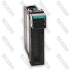
Allen-Bradley 1756-OB8 ControlLogix DC Digital Output Module | Original New | In Stock | View Details |

|
Allen-Bradley 1794-OB16P FLEX I/O Digital DC Output Module | Original New | In Stock | View Details |
Global Express Shipping
Returns & Warranty
Orders are processed and delivered Monday-Friday (excluding public holidays).
For full eligibility, restocking fees, and international return details, please view our official Refund & Return Policy .
| Color pattern |
White
Greyish White
|
| Country of origin |
Sweden
|
| Power source |
DC Power
|

A field checklist for separating 24 VDC input, carrier bus, output derating and alarm-contact faults before replacing an Emerson SE5009.

A controlled commissioning method for using the 140XSM00200 simulator to verify Modicon Quantum input mapping and interlocks before reconnecting field wiring.

A commissioning checklist for the ProSoft PLX32-EIP-MBTCP covering subnet separation, register contracts, EtherNet/IP timing, failure tests and replacement records.

A field checklist for IC693MDL916 relay commands, terminal blocks, load current, switching rate and contact-side measurements.

A field checklist for KL1512 signal thresholds, counter direction, process data and the KL1512-to-KS1512 wiring difference.

A field checklist for EPP2008-0001 current limits, supply voltage, channel LEDs, connector coding and load-related output faults.