Description
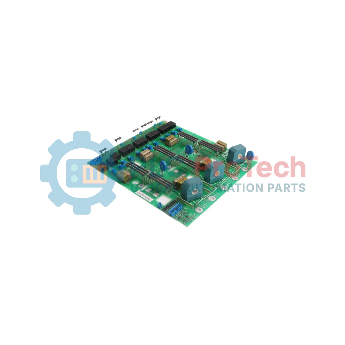
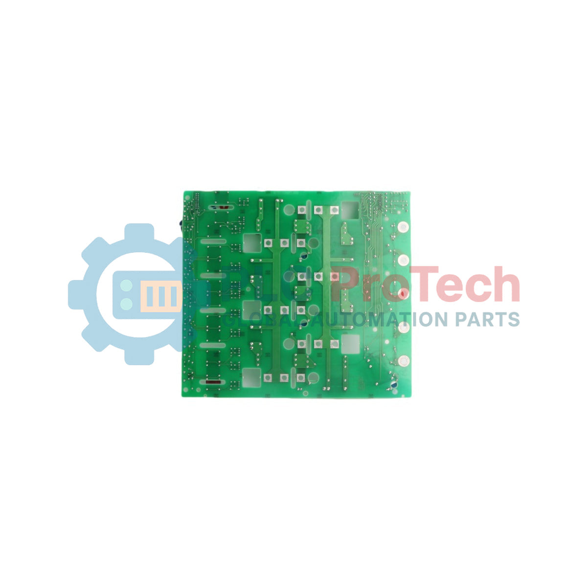
The ABB SDCS-PIN-11 is a high-reliability power interface circuit board engineered specifically for primary thyristor power converters and multi-drive industrial rectifiers. Operating as the foundational power interface board within the drive control assembly, this critical component acts as the galvanic and functional bridge between low-voltage microprocessing control electronics and the high-potential power semiconductors.
To maintain precise tracking and processing synchronization under heavy thermal and electrical loads, the SDCS-PIN-11 coordinates pulse transformer firing commands, snubber monitoring, and physical voltage sensing pathways. The hardware matrix, identified by part number 3ADT306100R0001, handles demanding pulse distribution and feedback signal tracking, ensuring continuous system stability and rapid fault containment within complex industrial DC drive infrastructure.
Features
-
High-Potential Pulse Isolation: Delivers reliable electrical separation between low-power logic gates and high-current SCR gating circuits.
-
Integrated Drive Diagnostics: Incorporates voltage and signal feedback infrastructure to continuously report dynamic circuit parameters back to the main controller.
-
Robust Power Management Architecture: Optimized to withstand high transient line disruptions and rapid current changes without signal distortion.
Applications
- Thyristor power bridge control, pulse transformation, and phase monitoring within ABB DCS series industrial converters.
- Heavy industrial deployments including continuous metal rolling mills, paper mill section line drives, and mine hoist operations.
Technical Specifications
| Parameter |
Specification |
| Manufacturer |
ABB |
| Model Designation |
SDCS-PIN-11 |
| Product ID / Order Number |
3ADT306100R0001 |
| Functional Group Designation |
Power Interface Board |
| Part Type Status |
Original / New |
| Country of Origin |
Finland (FI) / Germany (DE) |
| Shipping Weight (Calculated) |
0.66 kg |
| Package Dimensions (Calculated) |
260 mm x 180 mm x 75 mm |
Installation Guidelines
CRITICAL WARNING: HIGH VOLTAGE AND RESIDUAL CHARGE HAZARD
Completely isolate, disconnect, and lock out all AC bus voltages and secondary auxiliary inputs feeding the converter system. Internal bus capacitors retain hazardous electrical potential energy after main circuit de-energization. Allow a minimum of 15 minutes for safety bleed-down to execute, and verify a zero-voltage state with a certified multi-meter before making terminal or hardware structural contacts.
1
Attach an approved static protection grounding strap to your wrist and fasten the reference clip to a clean, unpainted surface of the industrial panel enclosure frame.
2
Carefully disconnect internal interface ribbon cables, control wiring, and power links from the legacy board while documenting exact layout and structural routing.
3
Position the replacement module accurately on the chassis standoff channels, fasten mounting screws to complete a solid structural ground path, and reconnect interface connections.