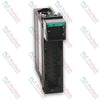
The ABB SPDSM04 is a high-performance Pulse Input Module developed for the Symphony Plus distributed control system architecture. Functioning within the S+ HR I/O (Harmony Rack) platform, this module offers 8 independent input channels optimized for capturing high-frequency pulse train signals ranging from 0 to 50 KHZ. It serves as a precision engineering interface for tracking rotational velocities, volumetric flow rates, and discrete industrial quantities directly from field transmitters and sensors.
Features
-
8 High-Frequency Input Channels: Accommodates multi-channel pulse processing on a single, space-efficient rack footprint.
-
Wide Dynamic Frequency Range: Processes pulse rates accurately from 0 up to 50 KHZ, supporting high-speed industrial measurement.
-
S+ HR I/O System Alignment: Integrates natively into standard Harmony Rack control topologies for low-latency bus communications.
-
DI Channel Categorization: Implements digital input conditioning circuitry adapted to withstand signal degradation and electrical noise over long cable runs.
Applications
- Turbine speed measurement, overspeed monitoring configurations, and shaft rotation verification.
- Interfacing with positive displacement, turbine, or vortex flowmeters emitting high-frequency pulse outputs.
- Industrial tachometer integration and conveyor velocity monitoring in heavy processing industries.
- High-speed piece counting and totalization systems across energy and manufacturing sectors.
Technical Specifications
| Manufacturer |
ABB |
| ABB Type Designation |
SPDSM04 |
| Channel Type |
DI (Digital Input / Pulse Input) |
| Number of Input Channels |
8 |
| Frequency Range |
0-50 KHZ |
| Product Net Depth / Length |
71.12 mm |
| Product Net Height |
358.14 mm |
| Product Net Width |
271.78 mm |
| Product Net Weight |
0.80 kg (Calculated) |
| Package Dimensions |
410 mm x 320 mm x 110 mm (Calculated) |
| WEEE Category |
5. Small Equipment (No External Dimension More Than 50 cm) |
| HS Code / Customs Tariff |
85389081 |
Installation Guidelines
CRITICAL WARNING: Completely isolate external signal sources and verify that all associated processing loops are loops-off before inserting or removing the card. Failure to safely isolate active signal grounds could result in electrostatic damage or unstable transients within adjacent slots.
1
Inspect the rear backplane connectors and matching subrack slot for any physical obstructions or contamination.
2
Slide the module down the upper and lower guide rails until it aligns precisely with the rear bus layout.
3
Apply uniform pressure to fully seat the hardware unit, then tighten the faceplate mechanical locking pins.
4
Connect the verified field signals to the designated termination terminal strips and confirm appropriate shielding continuity.