Product Overview
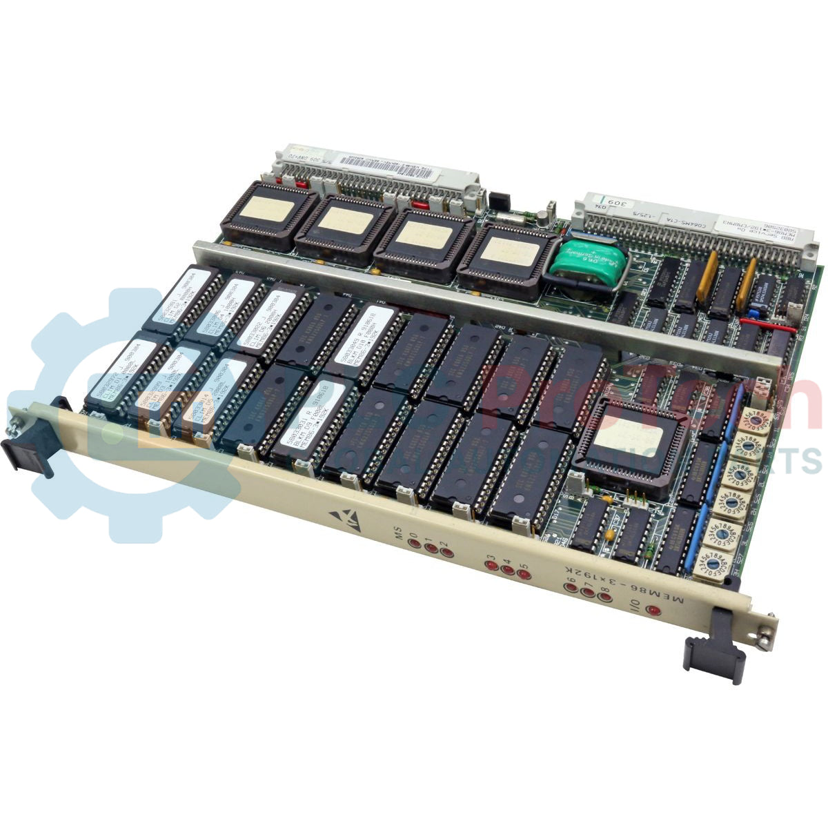
The MEM86-3X192K (MEM86-3*192K) is a high-density, general-purpose memory board designed specifically for the Allen-Bradley/Stromberg Digital Reference Controller (DRC) rack systems. Engineered to consolidate hardware footprints, a single MEM86-3X192K replaces up to three independent MEM86-192K legacy boards. This module provides a highly flexible architecture, supporting a hybrid mix of 32 Kbyte EPROMs for firmware, CMOS-type Static RAM (SRAM) for high-speed program storage, and EEPROMs for non-volatile program backup. By integrating Command Line Interpreter (CLIM) and Block Memory (BLKM) functionalities onto a single PCB, it optimizes rack space while enhancing the data processing reliability of high-performance motor drives and industrial control systems.
Technical Specifications
| Attribute |
Specification |
| Model |
MEM86-3X192K (3100-MEM) |
| Brand |
ABB / Stromberg (Allen-Bradley compatible) |
| Total Memory Capacity |
Up to 576 Kbytes (3 x 192 Kbytes) |
| Memory Types Supported |
EPROM (27256), SRAM (62256), EEPROM (28256) |
| Memory Mapping |
18 individually software-mapped 32 Kbyte groups |
| Word Length |
16-bit (requires circuit pairs per mapped area) |
| Power Consumption (Basic) |
+5 VDC @ 1.2 A (Typical for MS4 configuration) |
| Backup Battery |
Varta 100 DKO, 3.6 V, 100 mAH (Ni-Cd) |
| Operating Temperature |
0 to 50 deg C |
| Humidity |
5 to 95% (non-condensing) |
| Addressing |
3 independent I/O address areas via microswitches |
FAQs
What are the primary differences between the MS4, ME3, and MS5 configurations?
The 3100-MS4 is the basic memory board equipped with CLIM and Block Memory firmware. The 3100-ME3 serves strictly as a Backup Memory Board featuring high-capacity EEPROM storage. The 3100-MS5 is a hybrid "Basic + Backup" solution that combines firmware execution with EEPROM redundancy for critical parameters.
How is the onboard battery managed for SRAM data retention?
The onboard Ni-Cd battery is automatically charged whenever the rack is powered. It specifically maintains the voltage for low-power CMOS SRAM circuits during power-down. Note that the retention duration is highly dependent on ambient temperature; cooler environments extend the battery's self-discharge cycle.
Can I mix different memory chips in the same group?
Memory groups are mapped in pairs to achieve a 16-bit word length. Therefore, each pair of memory circuits (e.g., two 32 Kbyte chips) must be of the same type and speed to ensure synchronized data processing and prevent bus errors.
Does the board provide built-in voltage monitoring?
The board does not have onboard voltage supervision; instead, it relies on the /PWF (Power Fail) signal from the system bus. If this signal drops to a "0" state, all memory selection signals are inhibited to prevent data corruption during power instability.
Engineering & Installation Guide
-
Microswitch & Jumper Calibration: Before installation, you must verify the microswitch settings (S23, S25, S27) for the three I/O address areas. Because this board replaces three separate legacy boards, incorrect switch positions will lead to address conflicts on the DRC backplane.
-
Memory Mapping Logic: Address areas are separated by the most significant address bit (A14). Ensure that successive map addresses have their A14 bits in different states to avoid selecting the same physical circuit for two different software maps.
-
Thermal Management: For systems utilizing the battery-backed SRAM for critical data, maintain the enclosure temperature below 40 deg C whenever possible. High ambient temperatures significantly accelerate the self-discharge rate of the Ni-Cd battery and reduce its overall service life.
-
Firmware Replacement: When replacing EPROMs (firmware), ensure the chips are seated with the correct orientation in the sockets. Standard 27256 EPROMs should be handled using ESD-safe tools to prevent latent gate damage.