Product Overview
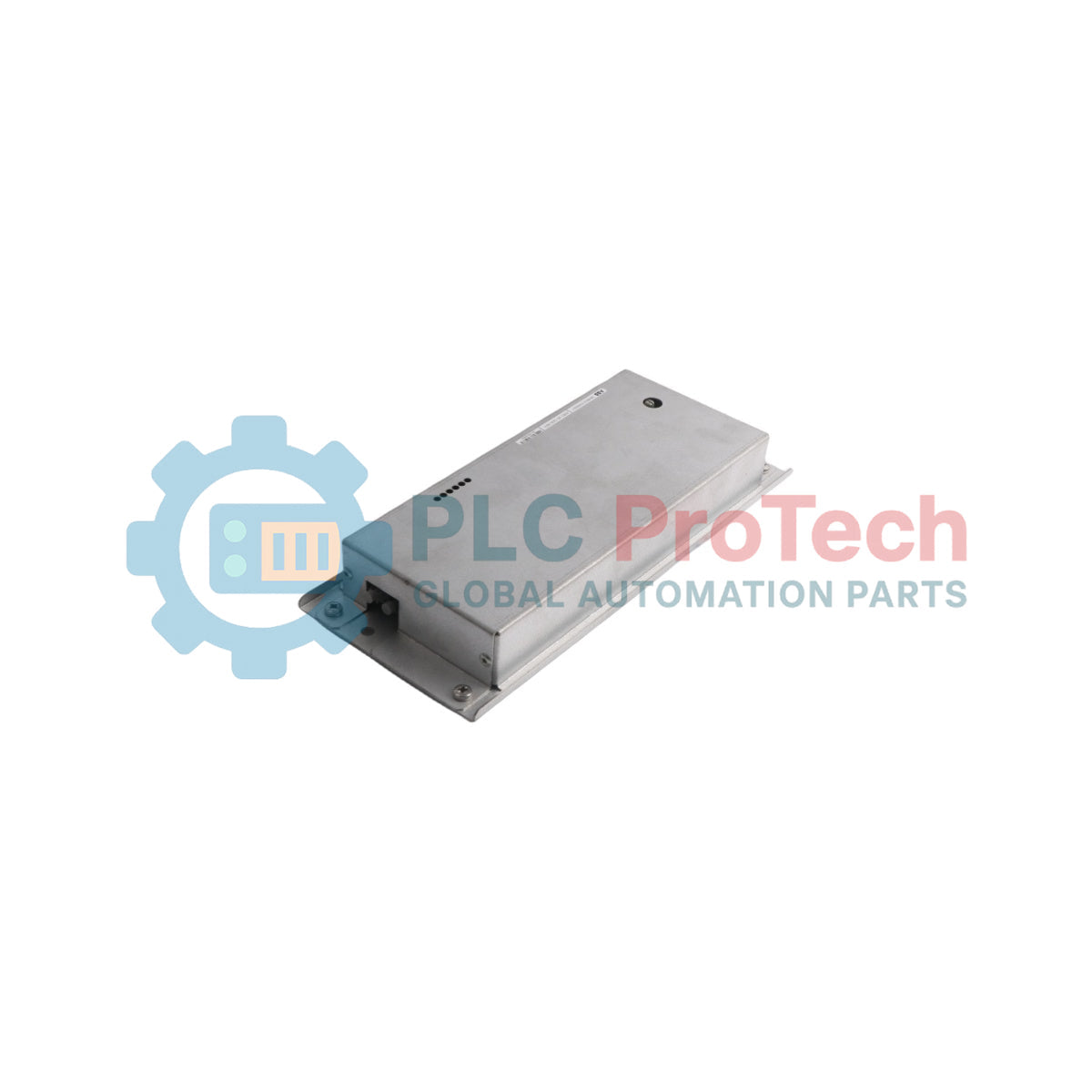
The ABB 3BHB022793R0001, officially designated as the ASE2 (UD C920 AE101), is a high-performance drive controller and digital communication module engineered for heavy industrial automation systems.
It primarily serves as a core communication and regulation processor within large-scale ABB UNITROL excitation systems and specialized high-power frequency converters.
This assembly includes the dedicated processor board enclosed within a protective housing to ensure mechanical stability and shielding from high-frequency electrical noise typical in power electronic environments.
The ASE2 (UD C920 AE101) module processes real-time control algorithms, regulates motor dynamics, and interfaces external bus communication protocols to maintain data synchronization between field devices and upper-level Distributed Control Systems (DCS).
Technical Specifications
| Attribute |
Details |
| Model |
ASE2 (UD C920 AE101) |
| Part Number |
3BHB022793R0001 |
| Brand |
ABB |
| Product Type |
Drive Controller Module / Digital Communication Unit |
| System Compatibility |
AC 800M Family / UNITROL Excitation Systems |
| Enclosure Type |
ASE2 with Integrated Housing Assembly |
| Operating Voltage |
220V Nominal |
| Memory Architecture |
Onboard ROM |
| Communication Interface |
Integrated Ethernet Protocol Link |
| Operating Temperature |
Max 55°C (Internal Cabinet Ambient) |
| Origin |
Switzerland / Sweden |
Ordering Information
Industrial procurement requires exact part number verification. Order replacements strictly by using the specialized Product ID and corresponding type definitions to ensure firmware and hardware compatibility.
-
Product ID: 3BHB022793R0001
-
ABB Type Designation: ASE2 (UD C920 AE101)
-
Alternative Variant Identification: UD C920 AE01
-
Packaging Form: Component integrated within original manufacturer housing
Engineering & Installation Guide
EMC Shielding and Backplane Isolation
The ASE2 (UD C920 AE101) handles high-speed digital control loop signals.
The integrated housing must be bolted directly to a clean, unpainted conductive mounting sub-panel inside the cabinet.
Ensure the rack enclosure has a low-impedance ground connection to the main electrical earth.
Keep all high-power motor cables and field excitation lines separated by at least 300 mm from the digital communication lines to minimize electromagnetic interference (EMI).
Firmware Verification and Hot-Swapping Protocols
This unit functions as a high-level central controller module.
It cannot be hot-swapped while the system drive bus or excitation network is under load.
Disconnect all primary and auxiliary 220V power sources before attempting hardware extraction.
When installing a replacement module, confirm that the onboard parameter configurations match the specific system application guidelines to prevent mismatched execution loops.
Thermal Dissipation Adjustments
Due to the continuous processing loops required by industrial drive regulation systems, the module generates localized heat inside the housing assembly.
Install the unit vertically within the cabinet card cage, leaving a minimum of 60 mm of free air space around the ventilation slots.
Ensure cabinet air filtration systems are maintained to keep internal ambient temperatures below 55°C.
FAQ
What system families natively support the ASE2 UD C920 AE101 module?
The module is primarily deployed inside ABB UNITROL systems for generator excitation control, alongside high-power industrial drives and process automation architectures that integrate with the AC 800M controller environment.
Does the 3BHB022793R0001 include the complete housing?
Yes. The 3BHB022793R0001 catalog specification details the complete ASE2 module pre-installed inside its standard industrial protective housing, shielding the inner circuitry from structural stress and physical contamination.
How do you diagnose basic communication faults on this unit?
Ethernet link connection status can be verified directly through the physical RJ45 port LEDs.
A solid green indicator confirms hardware link connectivity, while a blinking amber indicator denotes active data packets passing between the drive processor and the control station.