Overview
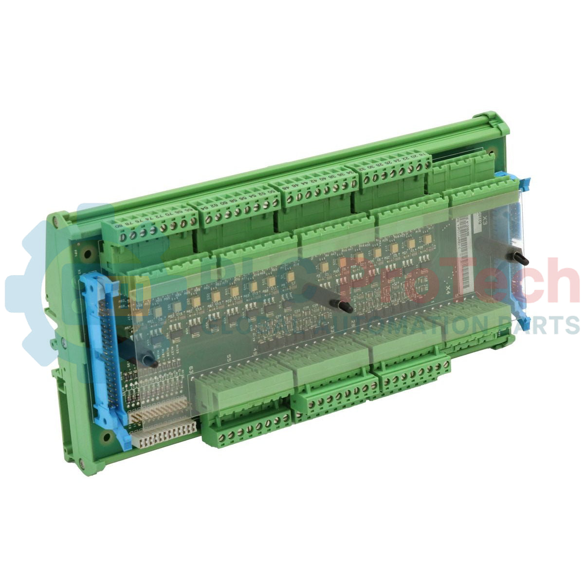
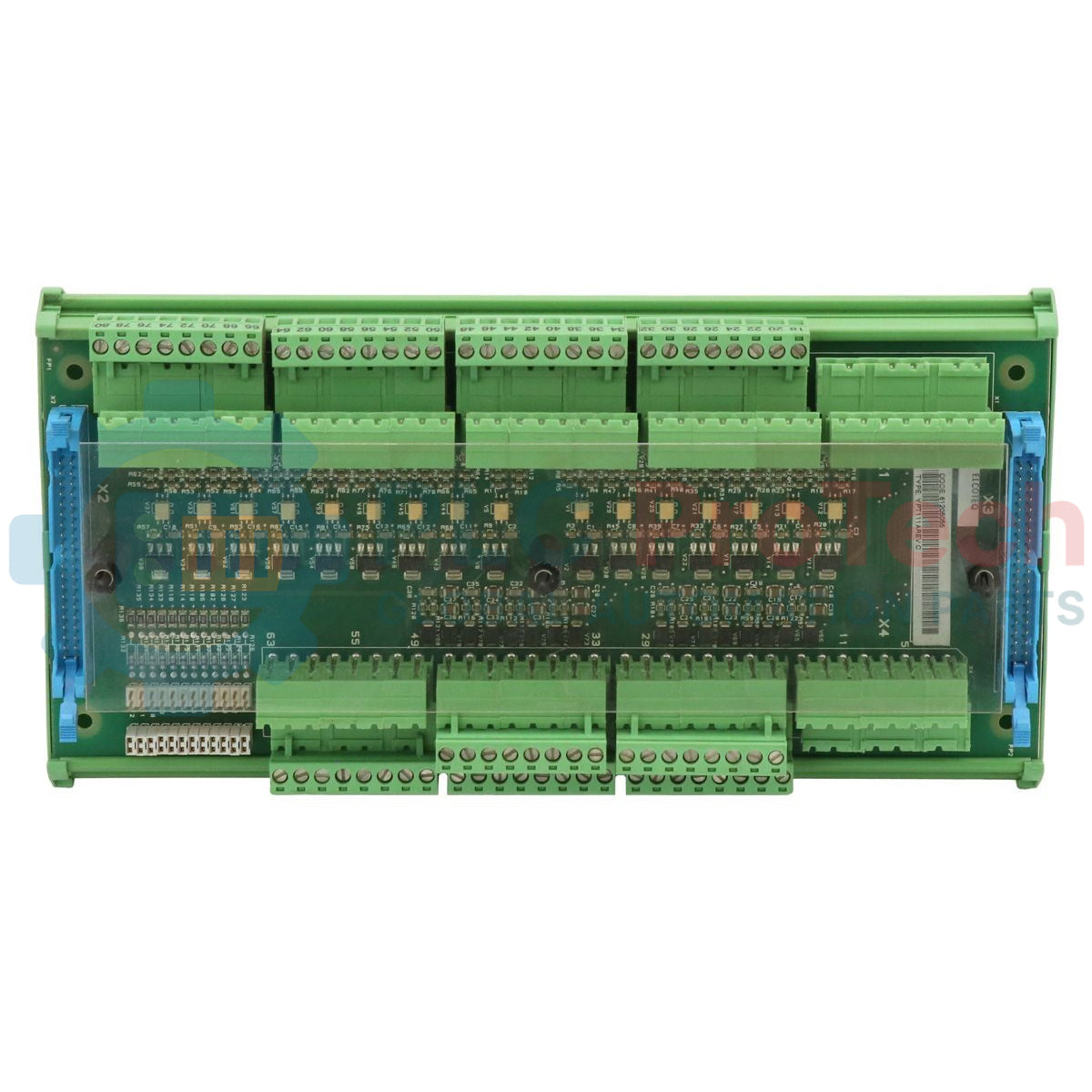
The ABB Stromberg YPT-111A (also designated as YPT111A) is an industrial-grade extended I/O terminal board engineered to act as the primary field instrument connection interface for the legacy Stromberg control system architecture. Operating alongside the YPQ-111A extended I/O processing board, this unit bridges field-level digital and analog instrumentation with core processing logic. In heavy continuous-process setups such as pulp and paper mills, metal processing facilities, and marine power distribution systems, signal termination failure can freeze critical telemetry loops. The YPT-111A addresses this by partitioning power distribution paths and organizing field signals before routing them through twin 40-pin flat ribbon connectors. This isolated interface layout significantly simplifies diagnostic access, prevents field-side surges from destroying master electronics, and helps reduce unscheduled system downtime.
Circuit Layout & Topology Configuration
The circuit topology of the YPT-111A centers on an independent, dual-bus power supply architecture managed via the main power connector X1. To minimize noise injection and cross-channel fault propagation, the board maintains two completely separate 24 VDC power rails. The first rail, labeled +24V IN / BI, supplies dedicated power to the binary input circuits across X1 pins 1, 3, 5, and 7. The second rail, labeled +24V IN, powers the associated YPQ-111A board exclusively when configured as a remote serial I/O node via pins 9, 11, 13, and 15. The hardware layout features four paralleled terminal positions per rail, allowing technicians to daisy-chain incoming power loops outward to adjacent YPT-111A or YPT-111B termination boards without installing external distribution blocks.
Hardware Parameter Matrix
| Parameter |
Performance Specifications |
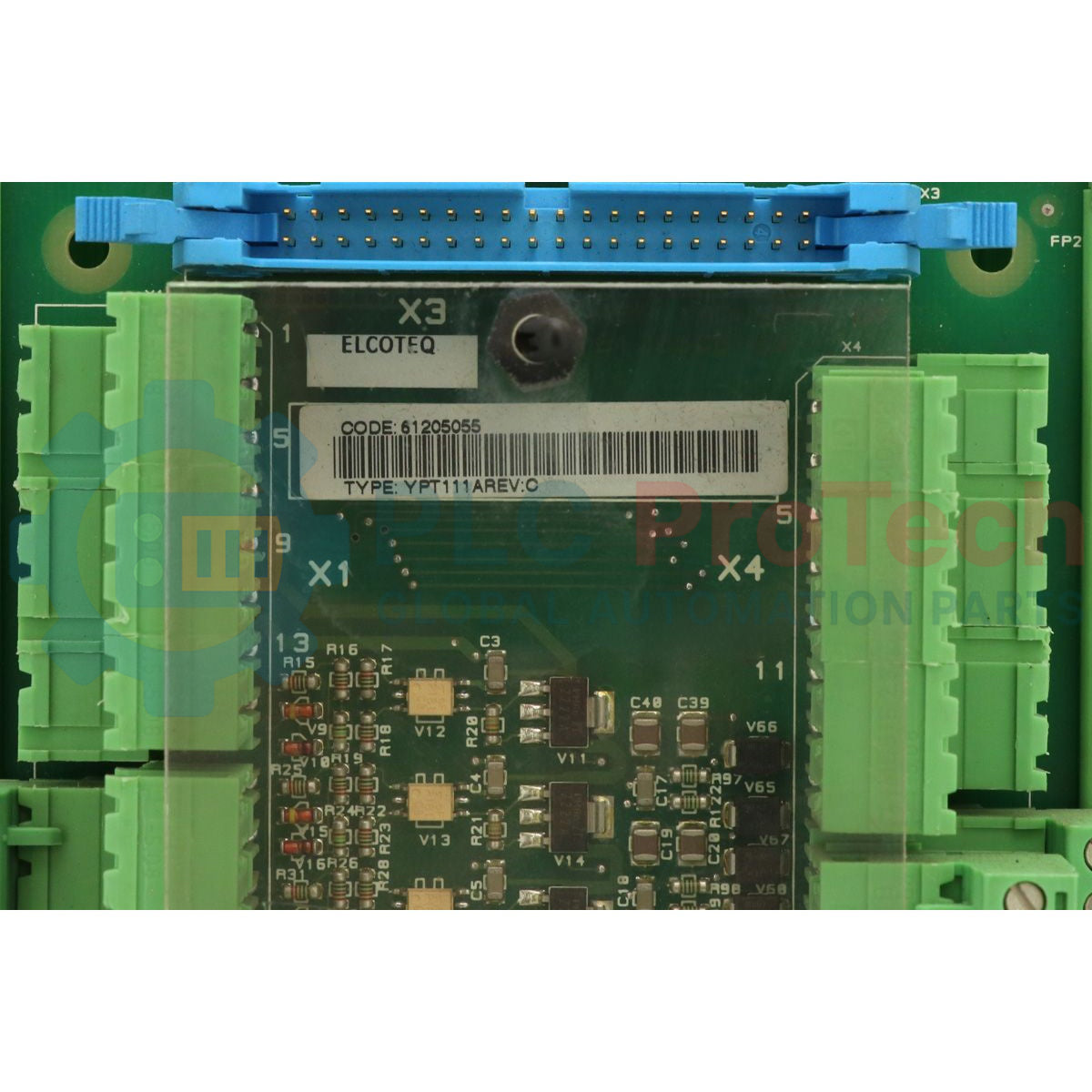
| Model |
YPT-111A (YPT111A) |
| Brand |
ABB Stromberg |
| Origin |
Finland |
| Component Class |
Extended I/O Terminal Board |
| Companion I/O Module |
YPQ-111A |
| Processing Interconnect |
Dual 40-pin flat ribbon cable interface |
| Discrete Voltage Input Rails |
2 independent 24 VDC inputs |
| Binary Input Power Terminals |
Connector X1: Pins 1, 3, 5, 7 (+24V IN / BI) |
| Remote Module Power Terminals |
Connector X1: Pins 9, 11, 13, 15 (+24V IN) |
| Loop Chaining Capacity |
4 internal loop-through points per supply rail |
| Master Control Platform |
YPP-110A Application Controller (via local backplane) |
| Operating Temperature Range |
0 to 55 deg C |
| Dimensions |
Standard Stromberg rack/panel termination footprint |
| Weight |
0.45 kg |
System Integration & Maintenance FAQs
Under what specific system condition must Pins 9, 11, 13, and 15 of connector X1 remain disconnected?
Pins 9, 11, 13, and 15 of connector X1 must never be connected or injected with 24 VDC power if the companion YPQ-111A board is running as local I/O. When configured locally, the YPQ-111A draws its operating power and routes logic directly from the parallel backplane connector of the YPP-110A Application Controller instead of using the serial remote bus option.
How does the daisy-chain power mechanism function across multiple termination boards?
The board provides four internal parallel connections for both the binary input rail and the remote I/O power rail. When chaining boards together, you bring the primary 24 VDC feed into the first terminal slot. The remaining three empty pins on that terminal block automatically function as parallel power outputs, allowing you to jumper the 24 VDC supply straight to the next block in series.
What type of cabling is required to connect the terminal board to the internal I/O module?
The interconnection requires two identical 40-pin high-density flat ribbon cables. These cables must be checked regularly for insulation wear or physical cracking, especially when deployed inside enclosures exposed to low-frequency industrial vibration.
Field Commissioning & Safety Wiring Guide
-
Ribbon Interconnect Seating: Turn off all control system power before attaching the dual 40-pin flat ribbon cables between the YPT-111A and the YPQ-111A card. Align the polar keys on both ribbon connectors with the matching socket slots on the board to avoid bending pins or causing pin misalignment.
-
Power Bus Separation: Verify that the 24 VDC field instrument supply (+24V IN / BI) and the remote logic supply (+24V IN) originate from isolated terminal sources if system isolation specs require separate circuit fusing. Do not short-circuit the distinct power buses on connector X1 during commissioning.
-
Chaining Limit and Overcurrent Safety: When daisy-chaining 24 VDC loops out to secondary YPT-111A or YPT-111B boards, calculate the cumulative current draw of all active binary loops. Ensure the combined load does not exceed the ampacity rating of the copper track or the primary supply fuse installed inside the panel.
-
Local Backplane Clearance: When using the YPQ-111A as local I/O connected directly to the YPP-110A Application Controller, ensure that no wiring drops or jumper leads make contact with pins 9 through 15 on connector X1. Insulate these terminal positions to prevent accidental short circuits during routine panel maintenance.