Overview
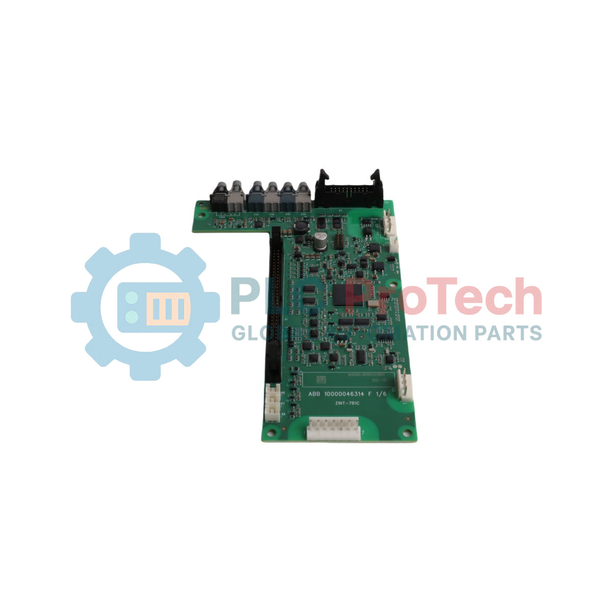
The ABB ZINT-7B1C (Product ID: 3AUA0000119630) is an internal printed circuit board (PCB) serving as the core main circuit interface for the ACS880, ACS580, ACH580, and ACQ580 series of variable frequency drives (VFD). Functioning at the critical junction between the power semiconductor stage and the main control unit, this board manages gate driver signaling, thermal feedback processing, and overcurrent sensing circuits. In high-demand process operations such as continuous mining conveyors, municipal water pumping stations, and large-scale HVAC air handling networks, a malfunction within the drive's internal signal interface stalls critical motors immediately. The ZINT-7B1C ensures ultra-low latency signal routing to secure gating precision under dynamic variable loads, playing a key role in stabilizing systemic performance and preventing catastrophic, un-programmed machinery shutdowns.
System Integration & Sourcing Architecture
The structural hardware topology of the ZINT-7B1C features an ultra-slim, multi-layer design tailored specifically for integration into compact drive power modules. Note that the raw ZINT-7B1C circuit board component is treated as a foundational sub-assembly rather than a direct, plug-and-play field spare part. Because modern firmware architectures dictate precise gate-pulse timings calibrated to specific IGBT ratings, this board must be deployed as part of an engineered kit or sourced via a fully pre-programmed option board assembly. It functions natively alongside designated ACS880-XINT and ACx580-XINT modules, delivering the necessary high-impedance galvanic isolation and logic voltage translation to safeguard low-voltage microprocessors from high-voltage DC bus transients.
Hardware Parameters Matrix
| Parameter |
Certified Specification Data |
| Model |
ZINT-7B1C |
| Product ID |
3AUA0000119630 |
| Brand |
ABB |
| Origin |
China |
| Classification |
Main Circuit Interface Board (PCB) |
| Device Category |
Internal Drive Component / Spare Sub-Assembly |
| Compatible Drive Platforms |
ACS880 / ACS580 / ACH580 / ACQ580 Series |
| Product Net Dimensions |
130 mm Height x 19 mm Width x 3 mm Depth |
| Product Net Weight |
0.15 kg |
| Gross Volume |
7.41 cm3 |
| Minimum Order Quantity |
1 piece |
| Functional Kit Grouping |
Component of Kits 3AXD50000004365 through 3AXD50000047311 |
| WEEE Compliance |
Product Not in WEEE Scope (Business to Business) |
Procurement Diagnostics & Engineering FAQs
Can the raw ZINT-7B1C board be purchased and swapped directly into an active drive?
No. This component is not direct-orderable as a standalone unprogrammed spare part. To perform a valid field replacement, maintenance engineers must cross-reference ABB document 4FPS10000485159 to source the correct, fully pre-programmed assembly. For ACS880 drives, select the pre-programmed ACS880-XINT package (3AXD50000155477); for ACx580 families, utilize the pre-programmed ACx580-XINT block (3AXD50001108335).
What happens if an unprogrammed or incorrectly programmed interface board is installed?
The master drive control unit will fail its startup self-test, generating an internal hardware configuration error or a communication mismatch fault. The drive will lock out firing pulses to the power bridge, preventing operation to shield the inverter stage from potential timing overlap damage.
Which specific pre-engineered maintenance kits contain this interface board?
The ZINT-7B1C board is a critical constituent of several manufacturer-certified repair and upgrade kits, including industrial kit reference numbers 3AXD50000004365, 3AXD50000024379, 3AXD50000030108, 3AXD50000030408, 3AXD50000037932, 3AXD50000037933, 3AXD50000047297, and 3AXD50000047311.
Component Replacement & Electrostatic Safety Guidelines
-
Electrostatic Discharge (ESD) Protection: The ZINT-7B1C houses highly sensitive complementary metal-oxide-semiconductor (CMOS) logic gates. Field technicians must wear a properly grounded ESD wrist strap before opening the drive module packaging or handling the board. Place the board exclusively on dissipative anti-static mats during workbench staging.
-
Bus Capacitor Discharge Verification: Prior to opening the drive housing or pulling out the existing interface layer, isolate the VFD from the main 3-phase AC grid. Wait for the designated discharge duration (typically 15 to 20 minutes depending on frame size) and verify with a calibrated digital multimeter that the DC bus voltage across the '+' and '-' terminals has dropped to 0 VDC.
-
Ribbon Cable Interconnect Tracking: Document and tag all low-voltage multi-pin ribbon cables and fiber optic lines leading to the board prior to disconnection. Inspect the micro-connectors for physical wear or contamination. When reassembling, ensure the lock tabs on the ribbon connectors are completely engaged to eliminate vibration-induced contact open circuits.
-
Fastener Torque and Standoff Integrity: Mount the board onto its non-conductive internal chassis standoffs with care. Tighten all internal M3 retaining screws to a maximum torque setting of 0.5 N-m. Over-tightening can cause micro-fractures in the multi-layer PCB traces, resulting in permanent, intermittent circuit failure under thermal cycling conditions.