Product Operational Summary
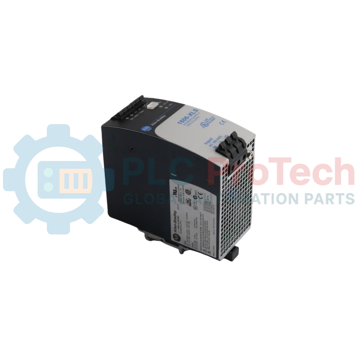
The 1606-XLS240E (1606XLS240E) functions as a high-efficiency power conversion station within the Allen-Bradley plant automation architecture, engineered precisely to the factory designation XLS Power Supply 240W 24VDC 10. Deployed across demanding heavy industries like petrochemical processing, automated automotive assembly lines, and high-capacity mining operations, this module stabilizes the critical 24 VDC control bus. By providing a built-in 150 percent short-term power reserve (PowerBoost), it releases up to 15 A of peak current for 4 seconds to overcome high inrush cycles from heavy inductive loads, such as DC motor brakes and large contactor coils. This rapid response capacity ensures uninterrupted controller operation, preventing erratic voltage dips and reducing critical system downtime.
Circuit Architecture and Engineering Features
The underlying topology of this XLS performance power supply integrates a synchronous rectification circuit with an active power factor correction (PFC) stage to deliver a nominal conversion efficiency of up to 93.5 percent. Its advanced universal input matrix accommodates both single-phase AC line inputs and steady DC source links without requiring mechanical toggle jumpers. For enhanced diagnostic visibility, the unit features an electrically isolated dry DC-OK relay contact coupled with a prominent front-panel LED status indicator, providing instant real-time health tracking to local PLC inputs. Built-in defense loops include continuous output overvoltage clamping, sustained short-circuit protection, and an automatic thermal shutdown mechanism that isolates critical internal components from severe field load faults.
Technical Specifications
| Parameter Metric |
Certified Technical Data |
| Model |
1606-XLS240E |
| Brand |
Allen-Bradley |
| Series |
Bulletin 1606 XLS Performance Power Supplies |
| Official Designation |
XLS Power Supply 240W 24VDC 10 |
| Continuous Power Output |
240 W |
| Nominal Output Voltage |
24 VDC (Factory calibrated at 24.1 VDC) |
| Output Voltage Adjustment Window |
24 to 28 VDC |
| Continuous Rated Output Current |
10.0 A @ 24 VDC
8.6 A @ 28 VDC
|
| Peak PowerBoost Reserve Current |
15.0 A @ 24 VDC (Up to 4 seconds maximum duration) |
| Input Voltage Range (AC line) |
100 to 240 VAC nominal (Operational limits: 85 to 276 VAC, 50/60 Hz) |
| Input Voltage Range (DC link) |
110 to 150 VDC nominal (Operational limits: 88 to 187 VDC) |
| Conversion Efficiency (Typical) |
93.5 percent @ 230 VAC input and full load |
| Power Losses at Full Load |
16.7 W @ 230 VAC input |
| Output Ripple and Noise (Max) |
30 mV peak-to-peak (20 MHz bandwidth limited) |
| Mains Hold-up Time Buffer |
46 ms @ 120 VAC / 47 ms @ 230 VAC |
| Isolation Barrier Rating |
Input-to-output: 3000 VAC
Input-to-ground: 1500 VAC
Output-to-ground: 500 VAC
|
| Diagnostic Relay Output |
Dry DC-OK Contact (Rated 60 VDC / 0.3 A, 30 VDC / 1 A, 30 VAC / 0.5 A) |
| Termination Connection Technology |
Quick-connect spring-clamp terminals (Toolless mechanical vibration-proof design) |
| Conductor Cross-Section Limits |
0.5 to 4.0 mm sq (20 to 10 AWG), solid or stranded wire |
| Operating Temperature Range |
-25 to 70 deg C (-13 to 158 deg F), linear current derating above 60 deg C |
| Enclosure Protection Rating |
IP20 |
| Mounting Mechanism Type |
Heavy-duty 35 mm DIN-Rail snap lock |
| Dimensions (W x H x D) |
60 x 124 x 117 mm (2.36 x 4.88 x 4.61 inches) |
| Weight |
0.90 kg (1.98 lbs) |
| Origin |
Germany |
Frequently Asked Questions
What specific field behavior does the PowerBoost feature target on this power supply?
The PowerBoost system allows the 1606-XLS240E to safely supply 15 A instead of its nominal 10 A current for a full 4 seconds. This temporary current increase is designed to satisfy the massive inrush current demands of inductive elements like DC motor starters or heavy solenoids, stopping the power unit from tripping or entering a protective current-limiting cycle during load activation.
Can two standard 1606-XLS240E units be directly paralleled to create an N+1 redundant rail?
Yes, but you must prevent a fault on one output from pulling down the entire control bus. To achieve a secure N+1 redundant layout, route the individual DC outputs of the two power units through an external diode isolation module, such as the Bulletin 1606-XLSRED series, before terminating at your main distribution blocks.
How does the DC-OK relay output function during an unexpected field overcurrent fault?
The DC-OK monitoring network continuously tracks the real-time output voltage. If an active short-circuit or massive overload drops the output potential below 90 percent of its calibrated value (approximately 21.6 VDC), the dry relay contact immediately opens and the front-panel green LED turns off, passing an active warning signal to your supervisory PLC logic.
Field Commissioning and Safety Declarations
-
Convection Thermal Clearances: The 1606-XLS240E relies entirely on natural convection cooling to keep internal components within safe operating thresholds. You must maintain precise clearance zones around the module casing: a minimum of 40 mm (1.57 inches) at the top ventilation grid, 20 mm (0.79 inches) at the bottom grid, and 5 mm (0.20 inches) on both side panels. Restricting this airflow profile will cause internal heat buildup and significantly reduce the operational life of the internal capacitors.
-
Vibration-Resistant Wire Termination: This power supply features quick-connect spring-clamp terminal arrays that resist mechanical loosening in high-vibration applications. Strip field wire insulation back exactly 10 mm (0.39 inches) before insertion. Use copper conductors rated for 90 deg C minimum with wire gauges between 0.5 and 4.0 mm sq (20 to 10 AWG). Ensure the Protective Earth (PE) terminal is securely linked to the enclosure backplate to enable the integrated EMC filter networks.
-
Branch Circuit Protection Coordination: To insulate the building grid against internal component failures, install a dedicated external circuit breaker upstream of the input terminals. An external 10 A or 16 A Type B or Type C miniature circuit breaker (MCB) must be implemented on the incoming single-phase AC line to handle initial power-up charging spikes without causing nuisance tripping.