Product Overview
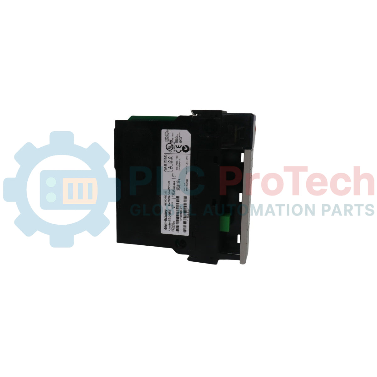
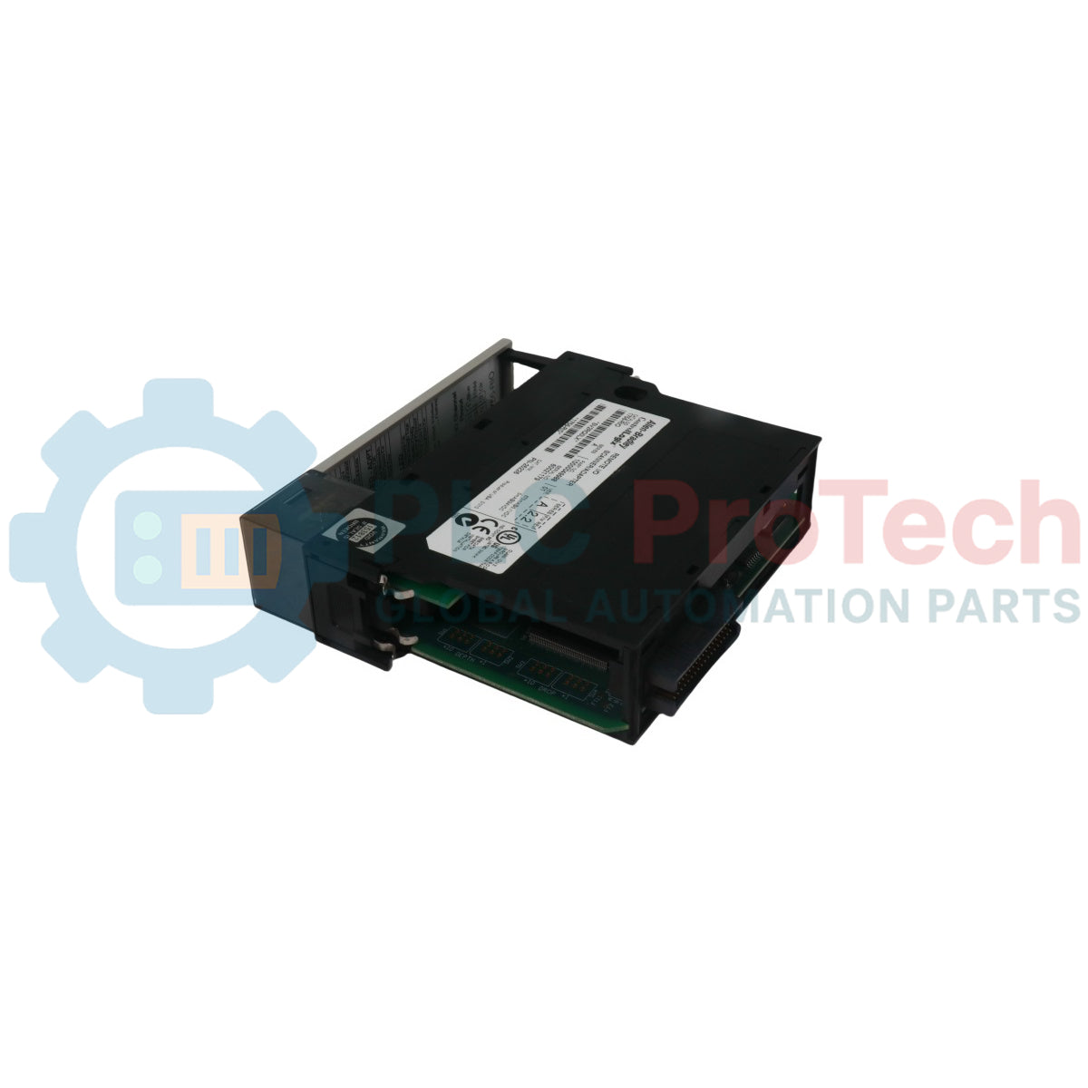
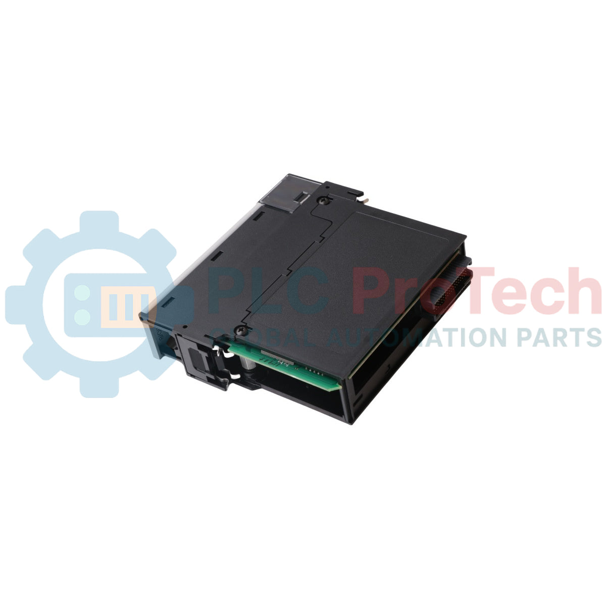
The 1756-RIO (1756RIO) is a ControlLogix Remote I/O scanner module developed by Allen-Bradley for bridging legacy Remote I/O networks with modern Logix controllers. The module enables a ControlLogix chassis to act as a scanner on classic RIO networks, allowing migration without replacing installed field I/O. It supports block transfer messaging, discrete data exchange, and rack addressing used in legacy PLC architectures. Engineers deploy this module in refineries, power generation facilities, and heavy material handling systems where phased upgrades reduce downtime. The 1756-RIO preserves installed infrastructure while enabling high-speed data exchange and deterministic control integration.
Technical Configuration
The 1756-RIO operates as a Remote I/O scanner within the ControlLogix backplane. The module communicates with legacy I/O adapters using blue hose Remote I/O cabling and supports standard rack addressing modes. It manages block transfer read and write instructions for analog and intelligent devices. The hardware supports selectable baud rates and flexible rack size configuration. The module handles discrete input and output mapping directly into Logix memory. It also supports partial rack addressing, improving compatibility with mixed legacy installations. Backplane communication occurs through the ControlLogix chassis, eliminating external gateway hardware.
Technical Specifications
| Parameter |
Specification |
| Model |
1756-RIO |
| Brand |
Allen-Bradley |
| Origin |
USA |
| Module Type |
ControlLogix Remote I/O Scanner |
| Backplane Current |
1.2 A at 5.1 VDC |
| Power Consumption |
6.1 W |
| Communication |
Remote I/O Blue Hose |
| Baud Rate |
57.6 kbps / 115.2 kbps / 230.4 kbps |
| Rack Addressing |
1/4, 1/2, 3/4, Full Rack |
| Discrete Capacity |
Up to 32 racks |
| Operating Temp |
0 to 60 deg C |
| Isolation |
30 V continuous |
| Weight |
0.32 kg |
| Dimensions |
145 x 35 x 140 mm |
Technical FAQs
Can 1756-RIO replace a PLC-5 RIO scanner directly?
Yes. The module functions as a scanner and communicates with existing Remote I/O adapters. Logix mapping must be configured.
Does the module support block transfer instructions?
Yes. The 1756-RIO supports block transfer read and write messaging for analog and intelligent I/O modules.
What cable type is required for Remote I/O communication?
The module uses standard Remote I/O blue hose cable with daisy chain topology.
Is the 1756-RIO compatible with ControlLogix redundancy?
Yes. The module supports redundancy when installed in mirrored chassis with identical configuration.
Engineering Installation Guide
Step 1: Verify Chassis Power Budget
Confirm the ControlLogix power supply supports the 1756-RIO current requirement. The module draws backplane current from 5.1 VDC. Check total chassis load before installation to avoid power supply overload. High density racks may require higher capacity power supply.
Step 2: Select Proper Slot Location
Install the 1756-RIO in a standard ControlLogix slot. Avoid placing the module next to high heat modules such as analog outputs or power supplies. Maintain airflow spacing inside the chassis for stable thermal performance.
Step 3: Configure Module Node and Baud Rate
Set the Remote I O baud rate to match existing adapters. Supported speeds include 57.6 kbps, 115.2 kbps, and 230.4 kbps. All devices on the Remote I O network must use identical communication speed.
Step 4: Prepare Remote I O Cable Wiring
Use approved blue hose Remote I O cable. Implement daisy chain topology only. Do not use star or ring wiring. Maintain consistent cable impedance across the trunk line.
Step 5: Install Network Termination
Install termination resistors at both ends of the Remote I O trunk. Improper termination causes communication retries and rack faults. Verify termination before applying power.
Step 6: Configure Rack Addressing
Match rack addressing with legacy Remote I O adapters. The 1756-RIO supports full rack, half rack, and quarter rack addressing. Incorrect configuration causes I O mapping errors.
Step 7: Grounding and Shielding
Connect cable shield to chassis ground at one point only. Avoid multiple ground connections. Route Remote I O cable away from motor drives and high voltage wiring.
Step 8: Insert Module into Chassis
Insert the 1756-RIO firmly into the backplane. Ensure top and bottom locking tabs engage fully. Loose seating may cause intermittent backplane communication faults.
Step 9: Power Up and Initial Diagnostics
Apply power to the chassis. Check module status LED. Verify scanner enters run state. Monitor communication counters and rack status.
Step 10: Commissioning and Validation
Download configuration from Studio 5000. Validate discrete mapping and block transfer messaging. Confirm all Remote I O racks update correctly. Monitor system for communication retries.