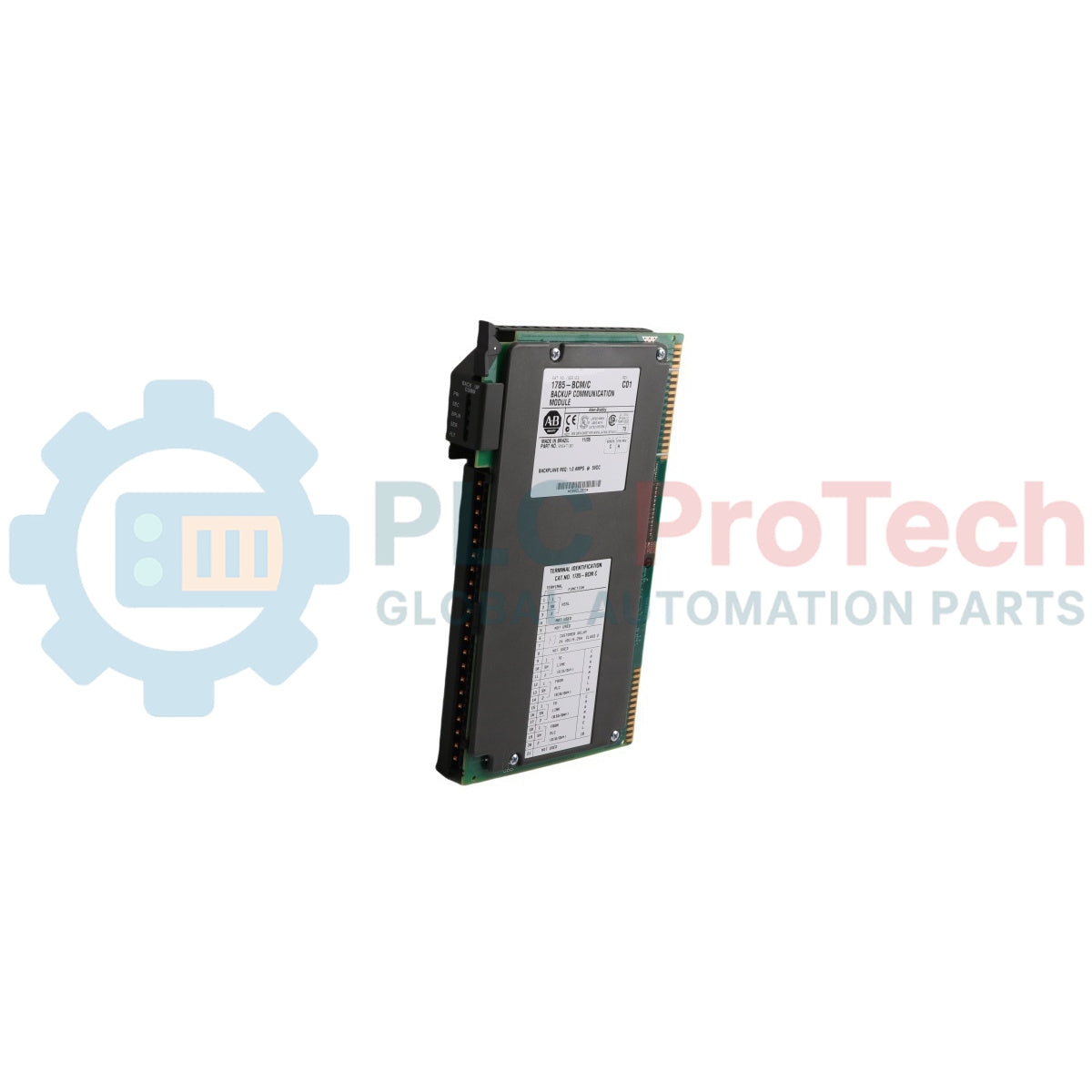
The 1785-BCM functions as a high-reliability hardware hot-backup module within the classic Allen-Bradley PLC-5 system architecture, officially designated as the PLC-5 Backup Communication Module. Engineered to provide high-availability system redundancy, it coordinates the synchronization of a dual-processor environment to prevent costly automation shutdown in continuous operations. Operating in primary/secondary pairs across twin local chassis, it tracks system health and handles the immediate, automatic takeover of field communications if a system failure occurs.
Redundancy Architecture and Operating Topology
The 1785-BCM establishes a hardware hot-backup network by cross-linking an active Primary System (which actively controls remote I/O and process equipment) to a synchronized Secondary System (held in a high-readiness standby state).
The system provides complete data alignment and immediate network recovery across three core communication mechanisms:
-
High-Speed Serial Link (HSSL): A dedicated inter-chassis differential communication pathway connected directly between the primary and secondary 1785-BCM modules. Running at a high-speed rate of 1.2 Megabits on Series B hardware (compared to 115 kbaud on legacy Series A units), the HSSL transmits remote input data, internal logic status, and user-defined data tables.
-
Smart Switch Remote I/O Interface: During standard runtime, the secondary processor is physically isolated from the field wiring but continues polling its local 1785-BCM. This module's integrated "Smart Switch" mimics real field nodes by populating the secondary processor's input image table with real-time data received across the HSSL. This architecture keeps the standby processor's logic memory completely identical to the primary unit.
-
Bumpless Switchover Execution: If the primary system experiences a power failure, a processor fault, a local 1785-BCM hardware error, or an intentional keyswitch mode change (e.g., from RUN to PROGRAM), a switchover is triggered. High-speed internal isolation relays on the primary module snap open, and matching relays on the standby module close. Control of the Remote I/O and Data Highway Plus networks transfers to the secondary processor in less than 50 milliseconds, keeping field outputs stable in their last state during the brief transition window.
Technical Specifications
| Parameter Metric |
Factory Manual Specification Data |
| Model Catalog Number |
1785-BCM
|
| Brand |
Allen-Bradley / Rockwell Automation
|
| Redundancy System Class |
PLC-5 Hot-Backup Core Communication Engine
|
| Backplane Current Consumption |
1.8 A maximum @ 5V DC
|
| Module Power Dissipation |
9.0 Watts maximum
|
| Thermal Load Dissipation |
30.7 BTU/hour
|
| HSSL Transmission Speed |
1.2 Mbps (Series B) / 115 kbaud (Series A)
|
| Integrated Communication Ports |
2 Configurable Channels (Channel 1A & Channel 1B)
|
| Supported Channel Networks |
Data Highway Plus (DH+) and Universal Remote I/O (RIO)
|
| Maximum Switchover Window |
$\le$ 50 milliseconds maximum
|
| Local Data Buffer Capacity |
4K Words for data table values
|
| Maximum Inter-Chassis Link Span |
Up to 152 meters (500 feet) utilizing 1770-CD line media
|
| Physical Enclosure Profile |
Open-style structural module housing
|
| Chassis Slot Allocation |
Occupies 1 Standard 1771 Universal I/O Slot
|
| Operating Temperature Range |
0 to 60 °C (32 to 140 °F)
|
| Storage Temperature Limits |
-40 to 85 °C (-40 to 185 °F)
|
| Relative Humidity Range |
5 to 95% non-condensing
|
System Compatibility and the 1785-BEM Expansion Module
-
Processor Compatibility Matrix: The 1785-BCM Series B (Revision C or later) supports an extensive range of PLC-5 platforms, including the PLC-5/11, -5/15, -5/20, -5/25, -5/30, -5/40, -5/60, and PLC-5/80. Legacy Series A modules are restricted strictly to older PLC-5/15 and PLC-5/25 processors.
-
1785-BEM Backup Extension Module: While the base 1785-BCM handles up to two on-board channels (Channels 1A and 1B), high-tier processors like the PLC-5/40 and PLC-5/60 support four communication channels. To protect these extra ports, the 1785-BEM Backup Extension Module must be installed adjacent to the BCM in the local rack. The 1785-BEM interfaces with the primary module across a local secondary backplane bus, expanding switching capacity to encompass Channels 2A and 2B.
Frequently Asked Questions
Can I use a 1785-BCM Series B module together with an older Series A module?
Yes. The Series B module retains backwards compatibility and can be paired with an existing Series A unit. To enable this legacy mode, you must explicitly set the physical configuration switches on Switch Assembly SW1 and SW2 on the side and bottom of the Series B module. If these match properties are omitted, the module status LEDs will flash an error code.
Can standard local industrial I/O modules be installed alongside the 1785-BCM?
No. The PLC-5 backup system is designed to switch and protect remote I/O networks; it cannot back up local I/O modules placed directly in the processor's main rack. To protect the process against disruptions, all control instrumentation must reside in remote I/O chassis, leaving the local chassis reserved strictly for the twin power supplies, processors, 1785-BCM, and optional 1785-BEM components.
What is the "Fast Data Transfer" mode on the 1785-BCM Series B module?
In standard synchronous operations, when block-transfer write (BTW) and read (BTR) instructions mirror user data tables across the HSSL, the secondary processor waits until an entire multi-block data segment is successfully received before making it available. Enabling "Fast Data Transfer" mode via Switch 2 on Switch Assembly SW1 allows the secondary module to instantly release individual blocks to the standby processor as they arrive. This shortens data table synchronization times significantly, dropping a 16-block (992 word) transfer time down from ~400–1000 ms to a fast 180–260 ms window.
Field Commissioning and Network Wiring Guidelines
-
Trunk Shield Isolation: Link the communication networks between the primary and standby chassis with high-grade 1770-CD "Blue Hose" shielded twisted-pair cabling. The copper shield drain wire must remain continuous across all intermediate connections and be firmly bonded to the main enclosure earth ground bus bar at only one physical end of the network loop. Grounding the shield at multiple spots creates ground loop noise that corrupts high-speed data transmission.
-
Asynchronous Block Transfer Logic: Because data table mirroring transfers operate asynchronously to the ladder program scan, process engineers should always use the instruction Done bit (
DN) of the primary BTR or BTW command as part of the interlocking execution logic. This practice ensures that intermediate or corrupt values are not transmitted to the standby system if the primary controller experiences a failure mid-scan.
-
Hazardous Isolation Protocol: The 1785-BCM is designed to permit live inspection and replacement of a faulted standby module without disrupting the online primary processor. However, if the hardware assembly is deployed in hazardous industrial zones (Class I Division 2 explosive atmospheres), you must entirely de-energize the enclosure power lines or confirm the area is completely non-hazardous before extracting modules or unseating any field wiring arms to prevent electric arc-flash ignition risks.