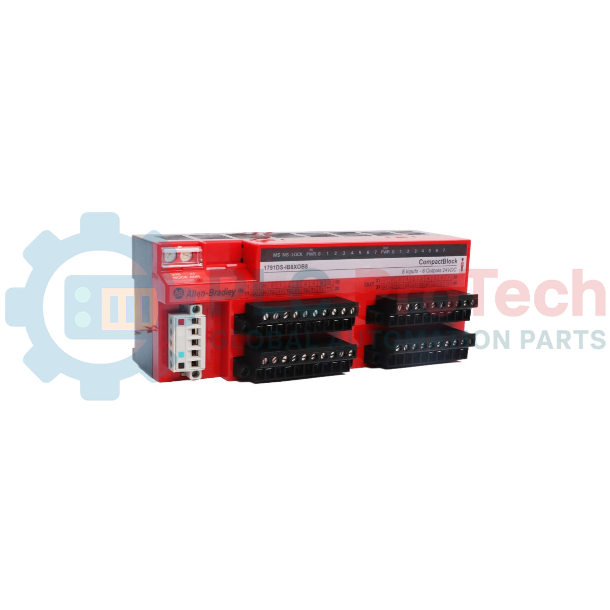
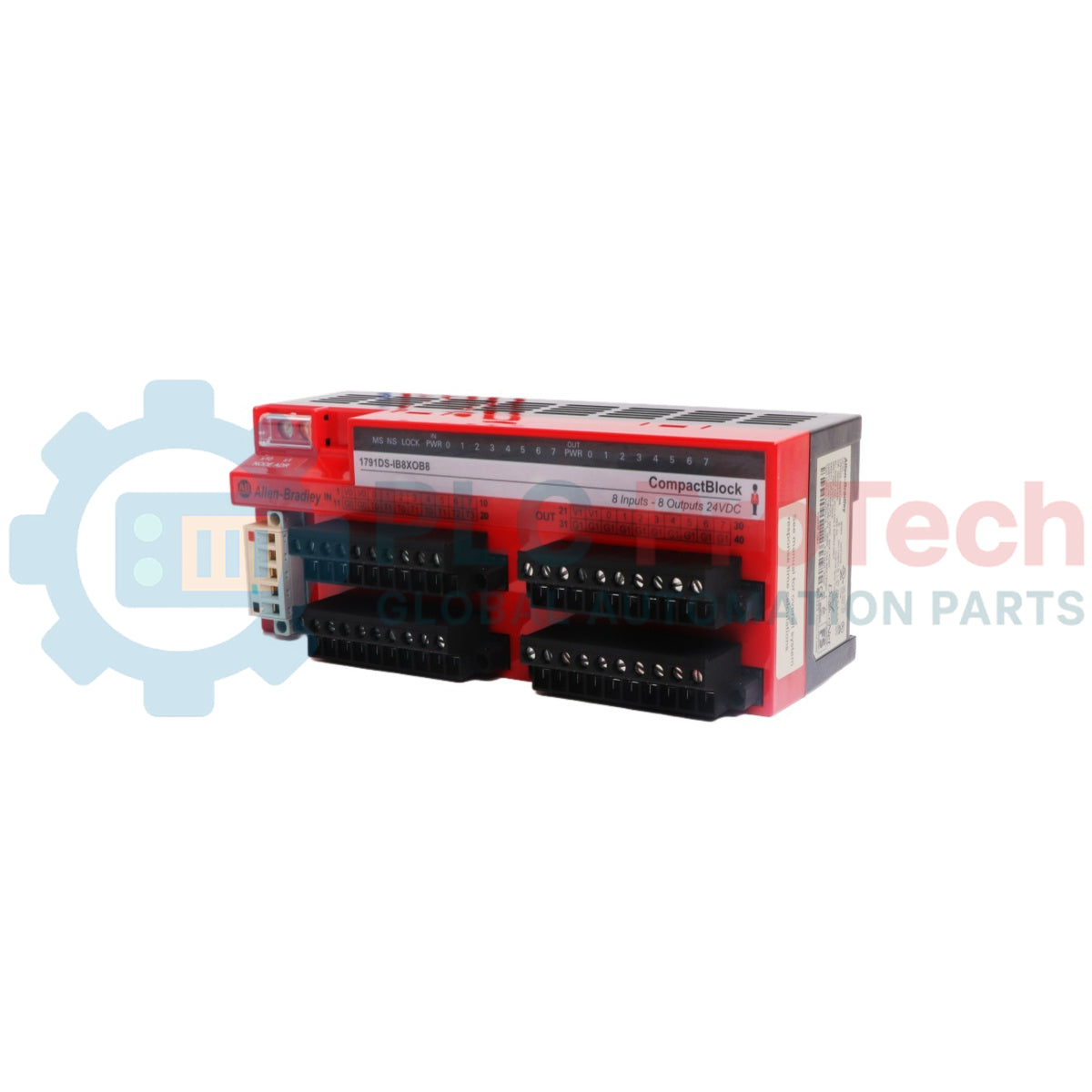
The 1791DS-IB8XOB8 is a distributed hardware block engineered for DeviceNet Safety architectures deploying the CIP Safety protocol. Operating as a decentralized station on standard networks, this solid-state block delivers functional safety interface management by encoding and decoding deterministic safety-state variables close to production field instrumentation. By providing built-in microcontrollers that execute automated cross-checking and diagnostic tests, the device isolates operating vulnerabilities to protect automation systems where the de-energized off-state governs safe machine criteria.
The physical enclosure contains an integrated combination layout featuring eight safety sinking inputs and eight safety sourcing solid-state outputs. The single-channel or dual-channel input paths accommodate dual-channel equivalence or complementary pairing topologies to fulfill strict emergency stopping or optical curtain tracking logic. The current-sourcing output points switch direct current voltage potentials outward to actuator loads up to rated margins. This module type communicates across central processors via network profiles managed in unified engineering software platforms.
Features
Eight safety-rated digital inputs for sinking circuit field tracking.
Eight safety-rated solid-state outputs operating in current-sourcing logic.
Standardized CIP Safety network capability directly across DeviceNet backplane lines.
Specialized test output points to deliver short-circuit cross-wire oversight.
Removable front-facing clamp connection blocks to sustain existing loops during replacements.
Matrix layout of dedicated LED status elements logging local, network, and power data.
Applications
Dual-channel emergency stop pushbutton station diagnostics.
Safety-critical gate monitoring and magnetic safety switch tracking.
Robot work cell access zoning and high-risk machinery stop circuits.
Technical Specifications
Parameter
Specification
Manufacturer
Rockwell Automation / Allen-Bradley
Brand
Guard I/O DeviceNet Safety
Part Number
1791DS-IB8XOB8
Module Type
16-Point Digital Combination Block Module
Number of Safety Inputs
8 Sinking Channels
Number of Safety Outputs
8 Sourcing Solid-State Channels
Number of Test Outputs
4 Sourcing Channels
Nominal Input/Output Voltage
24V DC
DeviceNet Supply Voltage Window
11V DC to 25V DC
Communications Current Consumption
110 mA at 24V DC
Sourcing Output Current Rating
0.5 A per channel maximum
Input Voltage (On-State)
11V DC minimum
Input Voltage (Off-State)
5V DC maximum
Enclosure Requirement Rating
IP54 (IEC 60529) or higher
Operating Temperature
-10 to 55 degC
Storage Temperature
-40 to 85 degC
Relative Humidity Range
5% to 95% non-condensing
Country of Origin
USA
Weight
0.42 kg
Dimensions
80 mm x 196 mm x 77 mm
Connections/Interfaces
Connector Pin
Function
I0 to I7
Safety Sinking Input Connection Nodes
T0 to T3
Test Pulse Monitoring Outputs
O0 to O7
Safety Sourcing Output Transistor Nodes
V, M
External 24V DC Auxiliary Operational Voltage and Return Rails
DeviceNet Terminal
Network Power and Communication Bus Line (V+, CAN_H, Shield, CAN_L, V-)
Installation Guidelines
DIN Rail Mounting
Hook the upper structural anchoring bracket of the module base directly onto a standard 35 mm wide industrial DIN rail. Align the bottom retention assembly and supply perpendicular force until the block snaps into a flux fit. Fasten rigid mechanical end plates at both boundary ends of the block array to preserve structural stability against mechanical sliding.
Minimum Air Ventilation Spacing
Leave a clear physical void zone extending at least 50 mm above and below the module outer casing walls. This continuous passage ensures natural convective thermal dispersion and leaves adequate structural clearance for routing large multi-conductor signal cabling bundles.
Safety Ground Termination
Run a short, heavy-gauge copper bonding lead from the local functional chassis earth terminal block straight to the master electrical control cabinet subpanel framework. Keep the ground pathway connection path as brief as possible to ensure maximum dissipation of surrounding high-frequency industrial noise.
Shield Treatment and Cable Handling
Connect the external DeviceNet communication cable metallic screen shield to a ground potential point strictly at the primary network power supply terminal. Never splice or common-tie the signal cabling or sensory input lines within shared wireways holding high-potential alternating current lines or heavy motor conductors.
FAQ
What constitutes the safety state of the inputs and outputs?
The safety state of both the data loops and physical hardware points is defined as the off-state.
Can the test output nodes be safely leveraged to power low-current auxiliary coils?
No, test outputs are not safety outputs and must never be applied as safety-rated drive connections.
What primary field hazard does the test pulse circuit address?
It allows continuous micro-intermittent signal line tracking to identify line cross-overs or direct wire-to-wire short circuits.
How are the device address values adjusted on this particular block?
The node address is set manually using the mechanical rotary switches accessible on the front panel assembly.
What configuration is required for the external DC power source supplying this module?
The primary direct current supply line must possess double or reinforced insulation properties to meet electrical safety mandates.
What is the minimum electrical threshold that registers as a logical on-state?
An incoming signal matches the logical on condition when the input voltage equals or exceeds 11V DC.
Does this model require specific cabinet provisions for open environments?
Yes, the hardware must be mounted in an electrical enclosure rated for IP54 or higher to keep out contaminants.
How do the front indicators reflect active fault states inside the hardware block?
The front-mounted MS and NS status lights alter color or flashing intervals to reveal distinct module faults or connection drops.
Can the input points handle two separate single-channel emergency stop buttons?
Yes, the software profiles allow configuring the points for independent single-channel operation rather than dual-channel monitoring.
What package format handles the physical data profiles for third-party tools?
Electronic Data Sheets provide the direct textual parameters required by configuration utility software.
Maintenance data connects work orders, sensor signals, asset history, costs, and technician knowledge. Used well, it improves planning, reliability, predictive maintenance, spare-parts control, and...
This article explains how integrated electric actuators, such as SMC’s e-Actuator series, are transforming industrial motion control by replacing traditional pneumatic and hydraulic systems. It...
This article explains how PLC systems perform core mathematical operations such as addition, subtraction, multiplication, division, modulo, and exponentiation within industrial automation. It shows...
The article explains several advanced Boolean logic functions used in PLC programming beyond basic AND, OR, and NOT operations. It covers how tools like truth tables, multiplexers, pulse generators,...
Boolean logic is the foundation of every PLC program. From simple machine controls to complex industrial automation systems, logic gates determine how controllers respond to changing inputs and...
Industrial firewalls play a critical role in OT cybersecurity, protecting PLC, DCS, and SCADA networks through segmentation, ingress/egress control, and IDS/IPS integration aligned with IEC 62443...
Choosing a selection results in a full page refresh.