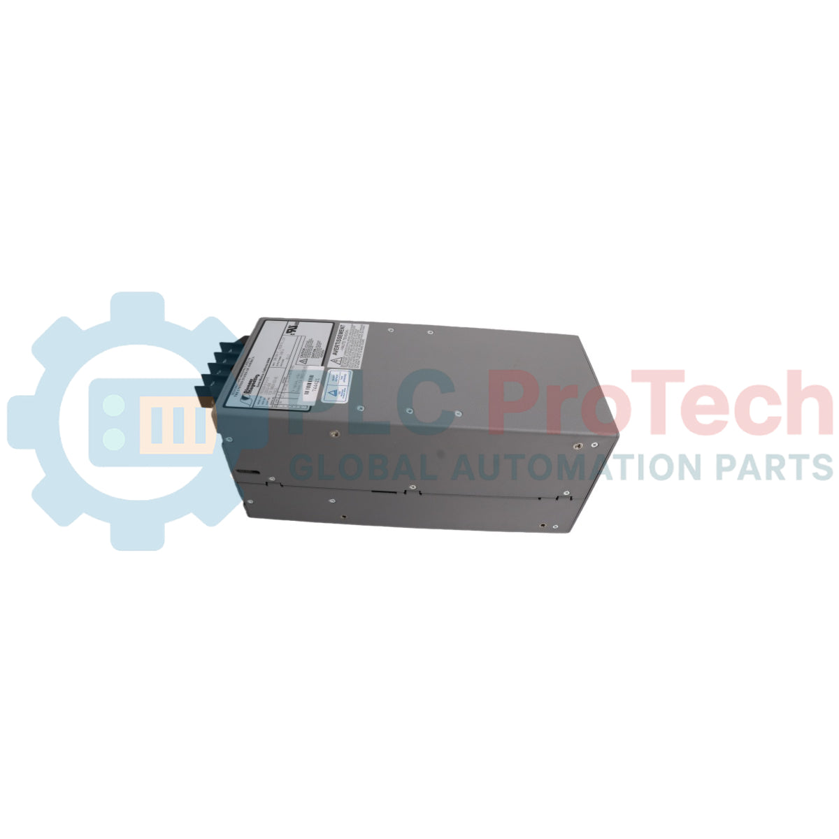
The Allen-Bradley PM3326B-6-1-2-E (Part Number 80026-529-01) is an industrial-grade internal control line power supply module engineered specifically for the 4th generation liquid-cooled PowerFlex 7000 Medium Voltage AC Drive platform. Functioning within the low-voltage control and cabling subsystem, this module is rated for normal duty cycles with integrated redundant supply provisioning as well as heavy-duty environments scaling from 3300V to 4160V up to 105A. The assembly converts core internal power distribution links to deliver regulated, low-noise DC control voltages and gate driver bias loops, supporting high-density SGCT PowerCage architectures and 4th generation vector control processor cards.
Features
-
Redundant Power Architecture: Dual-channel synchronization layout optimizes operational security by securing line supply transitions under high-load shifts.
-
Dual-Duty Optimization: Explicitly mapped for normal duty regulation and heavy-duty transient dampening in high-demand current loops.
-
Clean Bus Regulation: Integrates premium high-frequency filtering components to decouple downstream digital circuit rails from medium-voltage switching spikes.
-
Thermal Performance: Low thermal dissipation footprint engineered to match closed-loop liquid cooling system parameters within dense drive cabinets.
-
Rigid Standoff Integration: Reinforced structural metal chassis facilitates secure rack insertion inside the low-voltage section of the Control and Cabling Cabinet.
Applications
- Low-voltage control power distribution inside liquid-cooled PowerFlex 7000 Frame C drives.
- Main control voltage backup and redundancy management in medium-voltage industrial motor control centers.
- Heavy industrial high-torque processing plants including mining conveyors, large water pumps, and compressor control networks.
Technical Specifications Table
| Parameter |
Specification |
| Manufacturer |
Allen-Bradley / Rockwell Automation |
| Model Designation |
PM3326B-6-1-2-E |
| Product ID / Part Number |
80026-529-01 |
| Compatible Drive Platform |
PowerFlex 7000L Liquid-Cooled (Frame C) |
| Control Loop Configuration |
4th Generation Control System |
| Supported System Voltage Levels |
3300V / 4160V Systems |
| Maximum Operational Current |
Up to 105A Continuous |
| Supply Configuration |
Redundant Supply Architecture for Normal and Heavy Duty |
| Cooling Environment |
Liquid-Cooled Drive Core Adaptation |
| Country of Origin |
Canada |
| Shipping Weight (Calculated) |
4.20 kg |
| Package Dimensions (Calculated) |
320 mm x 240 mm x 150 mm |
Alternative Models & Compatibility
The PM3326B-6-1-2-E module functions as a critical system element within the 4th generation Série 7000L vector control framework. It provides backward firmware-level configuration compatibility when matching the 56V control supply profiles and 20V isolated gate driver power supplies (IGDPS) running on Frame C systems. It cannot be mixed with air-cooled variants or older 3rd generation control lines due to physical dimensions, thermal constraints, and specific connector layout dependencies inside the low-voltage backplane terminal rows.
Application Pitfalls & Engineering Notes
When running redundant supply loops on high-current networks up to 105A, cross-talk or parallel impedance changes between paired power supplies can cause fault triggering in the primary drive diagnostics. Always balance the incoming control voltages before placing the unit into a synchronized service state. Because this module is situated directly behind the main low-voltage tracking compartment in close physical proximity to the medium-voltage bus bars, ensure the internal plexiglass shielding partitions are perfectly re-seated to maintain proper air insulation boundaries.
Commissioning & Wiring Tips
During system commissioning, verify the input three-phase control power at the main internal circuit breaker or line disconnect (DS1) prior to re-energizing the drive processor. All internal DC control wiring and fiber optic cables must remain strictly isolated from AC lines using the integrated cabinet routing channels. Mixing low-voltage digital power and line voltage within the same tray or wire bundle can induce heavy electromagnetic noise, potentially causing transient errors on the Drive Processor Module (DPM) or creating sync errors between the rectifier and inverter sections.
Installation Guidelines
CRITICAL WARNING: HIGH TENSION HAZARD. Never attempt installation or removal of this power supply module while medium voltage is applied upstream or while the main contactors are engaged. Severe electrical shock, arc flash hazards, or equipment breakdown can occur. Isolate all primary utility links, bleed residual bus energy, and confirm the mechanical safety key interlock system is fully locked before accessing internal compartments.
1
Isolate the entire PowerFlex 7000 drive by disconnecting upstream medium-voltage lines and auxiliary control power, then engage the key interlock system.
2
Open the low-voltage compartment door of the Control and Cabling Cabinet and remove the inner protective insulation barrier panels.
3
Label and disconnect all terminal connection plugs from the faulty power supply card, ensuring wires are pulled clear from the tracking rails.
4
Loosen the chassis retaining screws, slide out the obsolete assembly, and position the replacement module securely onto the mounting standoffs.
5
Tighten the retaining fasteners to standard torque specs, re-engage the wiring headers, re-seat the protective panel shields, and close the cabinet.