Centralized Power Infrastructure Overview
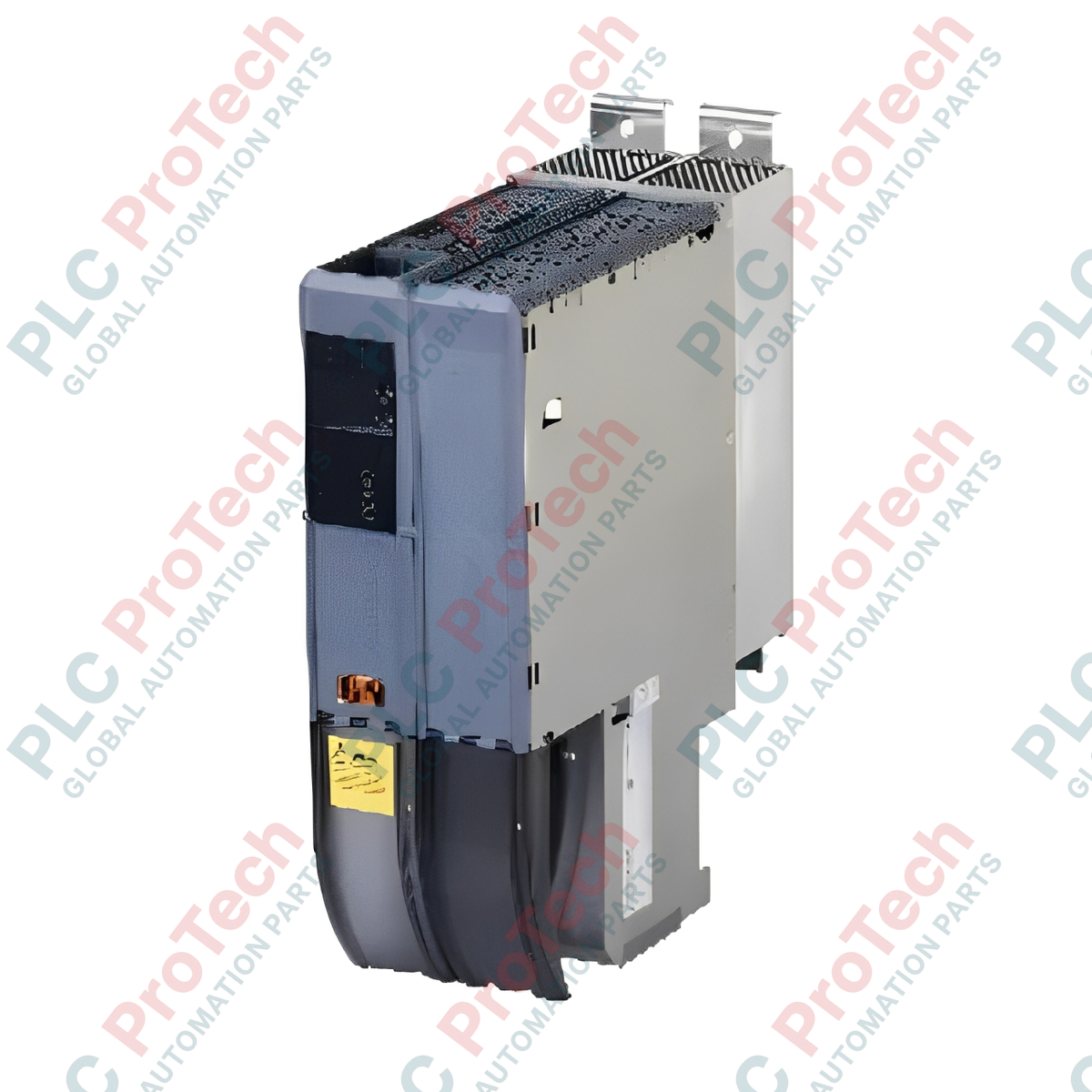
The 8BVP0440HW00.000-1 (8BVP0440HW00.000-1) is a high-capacity, high-voltage intelligent power supply module engineered by B&R Industrial Automation as the foundational energy matrix for the modular ACOPOSmulti drive platform. Rated at a robust 44 A continuous output current and configured for standard wall mounting, this primary power block rectifies incoming AC utility lines into a stable, high-efficiency 750 VDC intermediate circuit. In demanding, large-scale multi-axis motion control applications—such as robotic packaging lines, industrial blow-molding equipment, high-speed metal stamping presses, and automotive assembly grids—the 8BVP0440HW00.000-1 preserves absolute bus voltage stability and drives down unexpected asset downtime through a dynamic, regeneratively capable front-end topology. It actively balances energy across the internal backplane bus, harvesting braking energy from decelerating axes and distributing it to motoring axes natively.
Thermal Profiling & Switching Frequency Dynamics
The module utilizes advanced solid-state switching matrices whose efficiency and thermal dissipation are tightly bound to the configured carrier frequency:
-
750 VDC Energy Backbone: Generates and maintains a high-voltage DC bus designed to power multiple secondary inverter slices simultaneously via an integrated copper bus link.
-
5 kHz Switching Frequency Profile: Delivers high electrical efficiency with a thermal power dependency factor of 1.11 kW/K starting at an ambient threshold of 40 deg C. This setting minimizes switching losses under high continuous currents.
-
10 kHz Switching Frequency Profile: Provides ultra-smooth DC output filtration and reduced acoustic coil harmonics, operating with a thermal factor of 0.35 kW/K starting down at -10 deg C.
-
Dynamic Power Consumption Allocation: Manages a baseline logic power draw of 25 Watts, scaling dynamically to accommodate auxiliary loads from Option Slot 1 ($P_{SLOT1}$), Option Slot 2 ($P_{SLOT2}$), the external 24 VDC output terminal ($P_{24\text{ V Out}}$), and the mandatory 8BVF cooling fan assembly ($P_{Fan8BVF...}$).
Critical Engineering Parameters
The following specification overview details the mechanical, electrical, and environmental boundary limits verified for system engineering and cabinet integration:
| Parameter |
Specifications |
| Model |
8BVP0440HW00.000-1 |
| Brand |
B&R Industrial Automation |
| Origin |
Austria |
| Module Classification |
ACOPOSmulti Series Active Power Supply |
| Continuous Current Capacity |
44 Amps |
| Nominal Output Voltage |
750 VDC |
| Internal Control Input Power |
25 VDC (+/- 1.6%) | Input Capacitance: 4.7 microfarads |
| Maximum Internal Logic Draw |
25 W + Slot Cards + Fan Module Variables |
| System Backbone Variant |
ACOPOSmulti Backplane Plate Interface |
| Mounting Configuration |
Wall Mounting (Vertical Flange Grid) |
| Relative Humidity Limits |
Operation: 5 to 85% | Storage: 5 to 95% (Non-condensing) |
| Net Hardware Weight |
Approx. 5.50 kg |
| Shipping Weight |
6.50 kg |
Technical Knowledge Base & Common Inquiries
What specific functional advantages does the 750 VDC active power supply offer over standard passive diode rectifiers?
Standard passive rectifiers only permit one-way energy flow from the grid to the drive, dissipating excess braking energy as wasted heat through bulky dynamic braking resistors. The 8BVP0440HW00.000-1 features an active, controlled IGBT front-end that supports two-way power flow. When high-inertia servo axes decelerate rapidly, the power supply module acts as an inverter, syncing and feeding clean energy back into the facility's main AC grid, reducing total utility consumption.
How do the 5 kHz and 10 kHz thermal dissipation metrics impact control cabinet design?
The choice of switching frequency directly alters the thermal load inside the electrical enclosure. Running at 5 kHz scales down switching generation, allowing the hardware to safely withstand ambient air temperatures up to 40 deg C before requiring current derating curves. Toggling to 10 kHz matches high-performance positioning smoothness but shifts the thermal dissipation footprint, meaning derating calculations must begin much sooner to protect internal components from overheating.
Why is an internal 4.7 microfarad capacitance specified for the control logic feed?
The 25 VDC input feed drives the internal processor core, gate drivers, and option card electronics. The integrated 4.7 microfarad capacitance acts as a high-frequency filter, smoothing out local voltage dips caused by sudden switching demands or incoming noise on the 25 V line. This keeps the drive control loops operating deterministically without risk of logic dropouts.
Field Commissioning & Safety Guidelines
-
Vertical Cabinet Installation and Fan Modules: Mount the 5.50 kg power supply module strictly in a vertical orientation onto a flat, non-combustible metallic sub-panel. Because this unit relies on a companion 8BVF series mechanical fan block for forced-air thermal management, maintain a clear safety space of at least 100 mm above and below the module chassis. Monitor internal cabinet ambient air to ensure it stays within factory specifications.
-
High-Voltage DC Bus Bar Torque Specifications: When linking the shared 750 VDC copper bus bars across the power supply and adjacent inverter slices, tighten all retention screws to the exact torque limits defined in the B&R manual. High contact resistance from loose fasteners will cause extreme hotspots and high-voltage arc risks. Never work on the bus connections until a digital multimeter verifies that the DC bus has fully discharged below 42 VDC after power shutdown.
-
Mains Input and Control Cabling Separation: Route the heavy AC mains input lines and 750 VDC output bus bars through dedicated high-power wire ducts. Keep all low-voltage control signals, encoder lines, and 25 VDC logic power lines separated by at least 250 mm. Connect all power cable shields tightly to the sub-panel using low-impedance grounding clamps to safely divert common-mode noise away from nearby communications networks.