Product Overview
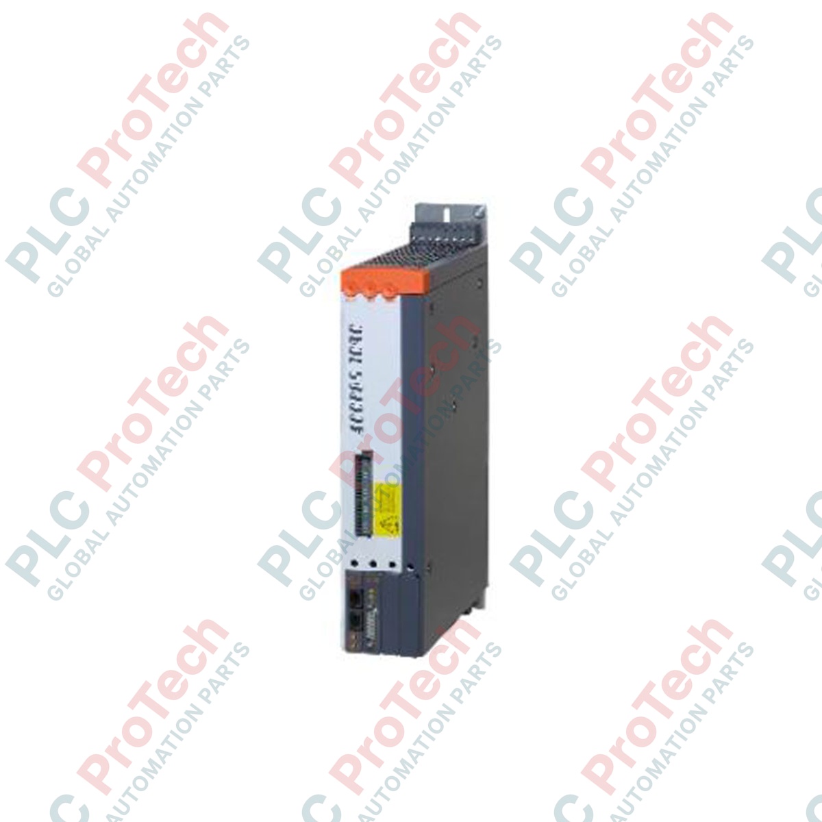
The B&R V1022.00-2 (V1022.00-2) is a compact single-axis servo drive belonging to the ACOPOS 1022 series, engineered for high-precision motion control in demanding industrial environments. It operates on a 3-phase mains input of 400 to 480 V AC and delivers a continuous output current of 2.2 A, supporting motors up to 1 kW. This drive is a core component in high-speed packaging machinery, printing presses, CNC machining centers, and robotic assembly lines where synchronized movement and minimal cycle times are critical. The unit integrates a line filter (EN 61800-3 Cat C3) and a braking resistor (3.5 kW peak) directly into the chassis, reducing cabinet footprint and external wiring complexity. An electronic secure restart inhibit prevents unintended machine startup after power restoration or fault clearing, enhancing personnel safety. With four expansion slots for plug-in modules (Encoder, I/O, Fieldbus), the V1022.00-2 adapts to complex feedback and communication requirements, ensuring maximum machine uptime and simplified maintenance via plug-in terminal connections.
Drive Configuration and Integrated Features
The V1022.00-2 utilizes a modular hardware platform designed for flexibility in panel layout and function expansion.
-
Power Stage: The drive handles an installed load of up to 3 kVA. It supports switching frequencies of 5, 10, or 20 kHz, allowing optimization between motor noise reduction and power loss. The DC bus capacitance is 235 uF.
-
Integrated Safety & Filtering: Includes an integrated RFI filter for mains input and an integrated braking resistor (130 W continuous, 3.5 kW peak) for managing regenerative energy during rapid deceleration or vertical axis movements.
-
Expansion Slots: Four front-facing slots accommodate ACOPOS plug-in modules. Common configurations include the AC114 (Encoder Interface) for EnDat/Hiperface feedback, AC119 (Digital I/O), or AC112 (Ethernet POWERLINK) for real-time communication.
-
Control Interfaces: Features 3 configurable digital inputs (24 VDC, sink) for limit switches and reference pulses, plus a dedicated Enable input. The motor interface supports temperature sensor (KTY84/NTC) and holding brake connections directly on the terminal block.
Technical Specifications
|
Parameter
|
Specification
|
|
Model
|
V1022.00-2
|
|
Brand
|
B&R Industrial Automation
|
|
Origin
|
Austria
|
|
Weight
|
Approx. 2.5 kg (Module only)
|
|
Dimensions
|
90 mm x 260 mm x 210 mm (W x H x D)
|
|
Operating Temp
|
5 to 40 deg C (Nominal), up to 55 deg C (With Derating)
|
|
Input Voltage
|
3x 400 - 480 V AC (+/- 10%), 50/60 Hz
|
|
Continuous Current
|
2.2 Aeff
|
|
Peak Current
|
14 Aeff (short-term)
|
|
Power Rating
|
1 kW (1.3 HP)
|
|
Installed Load
|
3 kVA max
|
|
Switching Frequency
|
5 / 10 / 20 kHz (Selectable)
|
|
Protection Class
|
IP20
|
|
Certifications
|
CE, cULus, KC, EAC
|
FAQs
Does the V1022.00-2 require an external line filter or braking resistor?
No. Unlike older generations or higher power models, the V1022.00-2 integrates both the mains line filter (Category C3) and the braking resistor internally. This saves significant panel space and reduces wiring time, though for extremely high duty cycle regenerative applications, an external resistor can still be connected to the DC bus terminals if needed.
What communication protocols does this drive support?
The base unit relies on the hybrid cabling system or optional plug-in modules. For standard operation, it connects via the B&R X2X Link or hybrid cable. For Ethernet-based control, you must install a plug-in module such as the AC112 (Ethernet POWERLINK) or third-party modules for EtherCAT/CANopen into one of the four front slots.
Is this drive compatible with third-party servo motors?
Yes, provided the motor parameters (current, inductance, back-EMF) are within the drive's rating (2.2 A continuous, 14 A peak) and a suitable encoder interface module is used. B&R recommends pairing with 8LS series servo motors for optimal performance, but the drive accepts resolver, EnDat, BiSS, and Hiperface feedback via the appropriate plug-in card.
What causes the "Derating" condition at higher temperatures?
Above 40 deg C ambient temperature, the output current capability decreases linearly (approx. 2.2 Aeff reduction per 15 deg C increase, depending on voltage setting) to prevent overheating of the power semiconductors. Proper cabinet ventilation or forced air cooling is required if operating consistently above 40 deg C.
Field Installation and Commissioning Notes
-
Grounding Integrity: The V1022.00-2 requires a low-impedance protective earth (PE) connection directly to the chassis using the designated M4 screw terminal. Use a star washer to penetrate paint or anodization. The PE conductor cross-section must match the power input conductors (min 0.75 mm2 / 18 AWG).
-
Clearance for Airflow: Maintain a minimum clearance of 80 mm above and below the drive to ensure proper convection cooling, as specified in the mechanical dimensions. Do not obstruct the top or bottom vent slots. If mounting multiple drives side-by-side, verify the cabinet ambient temperature does not exceed the derating curve limits.
-
Shield Termination: Motor power cables (U/V/W) and encoder cables must be shielded. Terminate the shield braid on both ends using the provided cable clamps or EMC glands to ensure a 360-degree low-inductance connection to the drive chassis and the motor housing. This minimizes EMI and prevents feedback errors.
-
Plug-in Module Handling: Always disconnect the 24 VDC control voltage and the main power before inserting or removing plug-in modules. Electrostatic discharge (ESD) protection is mandatory; handle modules only by their plastic housings or use a grounded wrist strap.