Advanced Embedded Process Control Overview
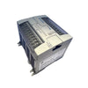
The X20CP1584 (X20CP1584) is a high-performance, industrial embedded controller engineered by B&R Industrial Automation within the flagship X20 System control architecture. Outfitted with a powerful computing core and extensive native fieldbus interfaces, this central processing unit manages highly deterministic machine automation and real-time multi-axis motion synchronization. In demanding plant floor installations—such as high-speed plastic extrusion lines, automated automotive assembly cells, precision semiconductor packaging machinery, and multi-tier logistics handling grids—the X20CP1584 ensures absolute process continuousness and curtails unexpected downtime through its ultra-fast processing cycle times, fanless thermal architecture, and comprehensive hardware diagnostics. Its modular backplane configuration allows for seamless localized or distributed I/O array extensions.
Native Communication Interface Portfolio
The controller housing integrates a comprehensive suite of hardware communication interfaces engineered for parallel networking and fieldbus connectivity:
-
Ethernet Platform: 1x standard RJ45 Ethernet port for plant-wide ERP/MES integration, localized HMI data exchange, and programming utility diagnostics.
-
POWERLINK (V1/V2): 1x real-time deterministic Ethernet port supporting POWERLINK V1/V2 protocols, facilitating synchronous motion control and sub-millisecond I/O updates.
-
X2X Link Bus: 1x integrated X2X Link master port providing the primary low-latency backplane bus link for localized expansion slices and remote decentralized I/O blocks.
-
Serial & Peripheral Support: 1x RS232 port for legacy peripheral interfaces or modem connections, alongside 2x USB ports for localized firmware updates and external logging tasks.
Critical Engineering Parameters
The following specification matrix details the core electrical, mechanical, and operational boundary limits verified for system architecture deployment:
| Parameter |
Specifications |
| Model |
X20CP1584 |
| Brand |
B&R Industrial Automation |
| Origin |
Austria |
| B&R ID Code |
0xC370 |
| Cooling Topology |
Fanless (Natural Convective Design) |
| Program Storage Interface |
CompactFlash Slot (Application memory deployment) |
| Integrated Diagnostics |
Active status LEDs for CPU, Network, Battery, and Temperature |
| Real-Time Clock Buffer |
Integrated Battery Backup System |
| Mounting Orientation |
Standard DIN Rail Alignment |
| Operating Temperature Range |
0 to 55 deg C (Standard enclosure buffer) |
| Net Structural Weight |
0.45 kg |
| Shipping Weight |
2.00 kg |
Technical Knowledge Base & Common Inquiries
What functional benefit does the fanless cooling design offer in harsh manufacturing zones?
By eliminating a mechanical cooling fan, the X20CP1584 prevents internal dust buildup and avoids the breakdown risks of moving parts. The CPU transfers heat out through an engineered internal sink setup using natural convective air currents. This design drastically lowers maintenance needs, making the module ideal for wood mills, textile plants, or high-vibration control panels.
How do the integrated hardware diagnostic LEDs simplify troubleshooting during process faults?
The CPU front panel includes dedicated diagnostic indicators linked directly to core hardware sub-systems (including CPU function, overtemperature, Ethernet, POWERLINK, CompactFlash, and battery status). If an overtemperature state develops or the real-time clock battery drops past a critical voltage limit, the hardware instantly updates the status LEDs and system error registers, allowing maintenance teams to pinpoint issues before a system crash occurs.
Is an external CompactFlash card required to run the application project?
Yes. The X20CP1584 does not contain internal user flash storage for the active Automation Studio project. A matched B&R industrial CompactFlash card must be inserted into the front slot to store the compiled machine logic code, hardware parameters, recipe arrays, and web server visualization files.
Field Commissioning & Safety Guidelines
-
Enclosure Thermal Management Clearances: Mount the X20 CPU base vertically onto a rigid 35 mm DIN rail inside the electrical control enclosure. To support optimal convective thermal air current tracking through the fanless chassis venting channels, preserve a strict minimum clearance boundary of at least 30 mm on both sides and 50 mm above and below the module block. Keep internal cabinet air safely inside the factory limits.
-
POWERLINK Real-Time Cable Layout: When running the POWERLINK interface at sub-millisecond communication cycles, utilize high-grade Category 5e (or better) double-shielded industrial Ethernet cables (SF/UTP). Route these real-time data networks through separate wire ways away from high-current AC power cables, motor power runs, or variable frequency drive (VFD) output wires by at least 200 mm to completely suppress electromagnetic noise injection.
-
System Grounding and Battery Maintenance: Connect the central DIN rail and mounting sub-panel directly to the facility's master low-impedance earth ground copper bus. When replacing the backup battery module, perform the switch while main system logic power is active to prevent wiping out the real-time clock parameters and volatile memory logs cached inside the controller.