Product Overview
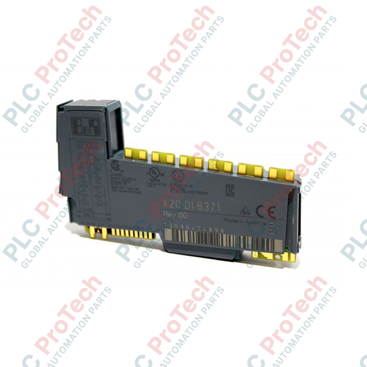
The X20DI6371 (X20DI6371) is a high-density digital input module integrated into the modular B&R X20 System architecture. Designed for reliable signal acquisition in industrial automation environments—such as assembly line controllers, conveyor tracking systems, and distributed I/O islands in manufacturing cells—this module provides 6 independent digital input channels. It operates on a standard 24 VDC logic level and supports flexible 1- or 2-wire connection topologies, allowing for streamlined wiring in space-constrained control cabinets. The module features integrated status LEDs for every channel, operating state, and module health diagnostics, ensuring rapid field troubleshooting and reduced maintenance downtime.
Technical Configuration
This module is engineered for robust signal isolation and consistent performance within the X20 backplane. It manages high-speed digital switching and provides precise status feedback for PLC logic execution.
-
Signal Flexibility: Each of the 6 digital inputs is compatible with 1- or 2-wire wiring configurations, allowing for versatile sensor integration across various field requirements.
-
Integrated Diagnostics: The front-facing diagnostic LED matrix provides immediate visual verification of I/O function per channel, current module operational state, and overall communication status.
-
System Integration: Fully compatible with the B&R X20 backplane, the module ensures low-latency signal transmission, critical for real-time process monitoring and interlock sequences in heavy machinery and automated production lines.
Technical Specifications
| Attribute |
Specifications |
| Model |
X20DI6371 |
| Brand |
B&R (Bernecker + Rainer) |
| Module Type |
Digital Input Module |
| Digital Inputs |
6 Channels |
| Nominal Voltage |
24 VDC |
| Wiring Capability |
1- or 2-wire connections |
| Status Indicators |
Individual channel, module state, and operating status LEDs |
| System Compatibility |
B&R X20 System |
| Operating Temperature |
0 to 55 deg C |
| Shipping Weight |
1.5 kg |
Industrial Hardware FAQs
Does the X20DI6371 support both sourcing and sinking sensor signals?
The module is designed to operate within the standard X20 input architecture. It is critical to ensure that your field sensors are configured to match the input logic voltage levels (24 VDC) specified for the B&R X20 input modules to avoid signal misinterpretation or potential damage to the input stage.
Can I replace the X20DI6371 without disconnecting the field wiring?
Yes, the B&R X20 system utilizes a modular design where the terminal block (the "bus module") stays wired on the DIN rail. You can release the locking mechanism to swap out the electronic module head for quick replacement during maintenance, provided the power is cycled according to safety standards.
What do the status indicators represent if a channel LED is flickering?
A flickering LED typically indicates an unstable signal or a contact bounce issue with the connected field device. If the LED status indicates a module error, cross-reference the diagnostic registers in your B&R Automation Studio software to identify specific I/O channel faults.
Field Commissioning and Safety Guidelines
Wiring and Connection Integrity
When terminating 2-wire sensors, ensure that the potential supply and signal return paths are properly shielded if the cable run exceeds 10 meters. Use ferrules on all stranded wire ends to prevent individual strands from causing shorts at the terminal block ingress points.
DIN Rail Mounting and Grounding
Always install the module on a grounded metallic DIN rail. The X20 module utilizes the rail contact to establish local earth reference, which is vital for suppressing EMI/RFI noise in environments populated by variable frequency drives or high-voltage contactors. Ensure the DIN rail surface is free of paint or oxidation at the contact point.
Diagnostic Monitoring
Utilize the onboard LED indicators as your primary reference during the initial commissioning phase to map physical I/O to your PLC application. If a channel remains inactive despite a proven 24 VDC signal at the terminal, check for proper grounding of the common return path before inspecting the module for internal hardware damage.