Technical Description and Application
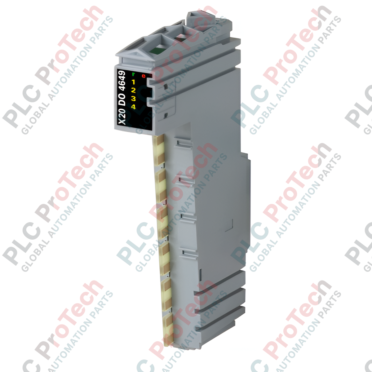
The X20DO4649 (X20DO4649) is a heavy-duty, 4-channel relay output module engineered for the modular B&R X20 System platform. Designed to bridge low-voltage controller logic with high-power field actuators, this module excels in harsh processing environments such as power distribution facilities, petrochemical plants, and heavy manufacturing lines. It features four independent normally open (NO) relay contacts capable of switching continuous loads up to 5 A at 240 VAC or 30 VDC. Each channel is built with complete single-channel electrical isolation, meaning that the individual outputs are entirely isolated from one another, from the internal system bus, and from the I/O power supply. This rugged configuration prevents cross-channel electrical faults from propagating through the automation rack, ensuring maximum system availability and mitigating the risk of catastrophic hardware failures.
Functional Architecture and Switching Performance
Operating across a flexible voltage spectrum, the module accommodates switching voltages up to 110 VDC or 264 VAC within a rated frequency range of DC and 45 to 63 Hz. The high-capacity internal relay contacts maintain a low initial contact resistance of under 100 mΩ, which minimizes localized thermal dissipation under maximum load conditions. While individual channels support a nominal current of 5 A, the module architecture mandates a strict total nominal current limit of 10 A across the entire unit to maintain thermal equilibrium inside the I/O stack. Onboard hardware diagnostic arrays utilize clear LED indicators to provide real-time updates regarding individual channel I/O functions, local operating states, and overall module health status.
Performance and Electrical Specifications
| Parameter |
Engineered Specification |
| Model |
X20DO4649 |
| Brand |
B&R (Bernecker + Rainer) |
| Module Category |
X20 System Relay Output |
| Number of Channels |
4 Outputs (Normally Open Contacts) |
| Output Isolation |
Single-channel fully isolated |
| Nominal Switching Voltage |
30 VDC / 240 VAC |
| Maximum Switching Voltage |
110 VDC / 264 VAC |
| Rated Operating Frequency |
DC / 45 to 63 Hz |
| Nominal Output Current |
5 A per channel |
| Total Summation Current |
10 A max per module |
| Peak Inrush Current |
Max. 5 A |
| Contact Resistance |
Max. 100 mΩ |
| Actuator Power Supply |
External sourcing required |
| Status Indicators |
LED indicators for Channel, State, and Module |
| Operating Humidity Bounds |
5 to 95% non-condensing |
| Country of Origin |
Austria |
| Gross Shipping Weight |
2.0 kg (Including robust heavy-duty packaging) |
Engineering Integration FAQ
Can the X20DO4649 mix AC and DC loads on different channels of the same module?
Yes. Because every channel is completely electrically isolated from the others, you can switch a 240 VAC motor starter coil on Channel 1 while simultaneously switching a 24 VDC indicator lamp loop on Channel 2 without any danger of cross-phase coupling or leakage current.
What is the function of the external actuator power supply requirement?
The internal X20 system bus only provides low-power logic signals to trip the internal relay coils. The actual energy used to drive the downstream field components (valves, contactors, alarms) must be supplied by an external power source wired into the relay contacts.
How does the module signal a mechanical relay failure?
The module registers functional diagnostics on the system bus. If the internal logic state commanded by the CPU does not align with the voltage state monitored across the internal relay coil drive circuit, the module reports a status error code to B&R Automation Studio and illuminates the local error LED.
Field Commissioning and Safety Protocols
-
Inrush Current and Surge Suppression Control: Relay contacts are susceptible to arcing and material pitting when switching highly inductive or capacitive loads. When controlling heavy inductive devices such as AC solenoid valves, install a properly matched RC snubber circuit across the contacts. For DC inductive loads, use a freewheeling diode to absorb high-voltage inductive spikes during turn-off cycles.
-
Total Current Budget Management: Ensure that the cumulative current drawn by all four channels does not exceed the total nominal limit of 10 A. If your application demands that three channels carry 4 A concurrently ($4\text{ A} \times 3 = 12\text{ A}$), you will exceed the module thermal limits; in such scenarios, distribute the load across multiple X20DO4649 modules.
-
Terminal Cabling Standards: Strip field wires carefully and use high-quality crimped ferrules to prevent fraying strands from bridging the narrow gap between adjacent isolated terminal blocks. Secure all high-voltage connections firmly within the spring clamps to minimize point resistance and eliminate localized heat spots.