Technical Description and Gateway Routing Logic
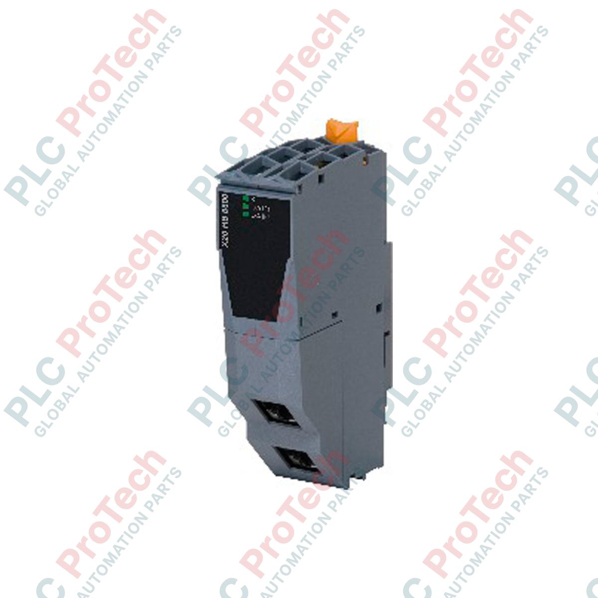
The X20HB8815 (X20HB8815) is an industrial-grade communication gateway designed for the modular B&R X20 System platform. This module functions as a highly efficient POWERLINK controlled node that bridges deterministic, real-time industrial Ethernet loops with standard non-real-time TCP/IP network infrastructures. It is engineered for complex automation applications—such as large-scale automotive assembly lines, municipal water distribution systems, and power plant control architectures—where field-level sensor and drive data must be routed transparently to higher-level SCADA, MES, or enterprise networks. The underlying hardware architecture includes an integrated expansion interface featuring up to two dedicated slots for hub expansion modules, allowing plant engineers to scale local network topologies dynamically without adding separate standalone switch hardware.
Network Interface and Electrical Architecture
The physical interface of the gateway features two shielded RJ45 ports that support standard segment line lengths up to a maximum of 100 meters between communication stations. The module manages two distinct network layers through these ports: a high-speed, real-time POWERLINK channel operating at a fixed transfer rate of 100 Mbit/s, and a standard TCP/IP channel with auto-negotiating 10/100 Mbit/s capabilities. Built for continuous operation inside high-density electrical enclosures, the module maintains a low thermal signature by drawing a maximum power consumption of 2 W from the backplane bus. Onboard diagnostic arrays feature clear LED status indicators that provide real-time visual updates for overall module health status and active bus communication function.
Performance and Network Specifications
| Parameter |
Engineered Specification |
| Model |
X20HB8815 |
| Brand |
B&R (Bernecker + Rainer) |
| Module Category |
X20 System Communication Gateway |
| Node Function |
POWERLINK Controlled Node |
| Expansion Capability |
Up to 2 slots for hub expansion modules |
| Physical Interface |
2x Shielded RJ45 ports |
| Max Segment Length |
100 m between 2 stations |
| POWERLINK Transfer Rate |
100 Mbit/s |
| TCP/IP Transfer Rate |
10 / 100 Mbit/s (Auto-negotiating) |
| Power Dissipation |
Max. 2 W |
| Hardware Diagnostics |
Onboard LEDs for Module Status and Bus Function |
| Country of Origin |
Austria |
| Gross Shipping Weight |
1.5 kg (Enclosed in electro-static discharge shielding) |
Engineering Integration FAQ
What is the primary architectural purpose of deploying the X20HB8815 gateway?
The module acts as a managed firewall and data bridge between your real-time machine control loop (POWERLINK) and your plant network (TCP/IP). It permits parameters, diagnostic traces, and operational data to be extracted by external software without allowing standard network broadcast storms to disrupt the microsecond-level synchronization of the machine drives.
How do the two expansion slots on the gateway function?
The two integrated expansion slots accommodate auxiliary X20 hub expansion modules (such as fiber optic interfaces). This lets you customize the physical media types and port density directly on the gateway node, bypassing the need for an external standalone industrial switch.
Can this gateway function as a POWERLINK Managing Node (Master)?
No. The X20HB8815 is strictly designated as a POWERLINK Controlled Node (Slave). It requires a primary X20 CPU or an advanced master controller to manage the cyclic network scheduling across the local bus segment.
Field Commissioning and Deployment Guidelines
-
Shielding and Cable Routing Integrity: Because POWERLINK communicates at high speeds, you must use industrial-grade Category 5e (or higher) double-shielded twisted-pair (S/FTP) cabling. Ensure the outer metal braid of the RJ45 connector makes clean contact with the shielded socket of the X20HB8815 to provide a low-impedance path to ground, preventing electromagnetic interference (EMI) from corrupting the real-time data packets.
-
Expansion Module Installation Safety: Prior to inserting or removing hub expansion modules into the auxiliary slots of the X20HB8815, completely isolate the 24 VDC power supply to the local X20 rack. Modifying the hardware layout while the backplane is powered can cause micro-arcing on the connector pins, which can permanently damage the internal routing logic.
-
Network Segmentation Layout: When configuring the TCP/IP interface for SCADA or MES data access, map out your IP address allocations carefully in B&R Automation Studio. Keep your real-time process image variables separated from heavy asynchronous data transfers to maintain low jitter and deterministic performance across the primary POWERLINK network segment.