Description
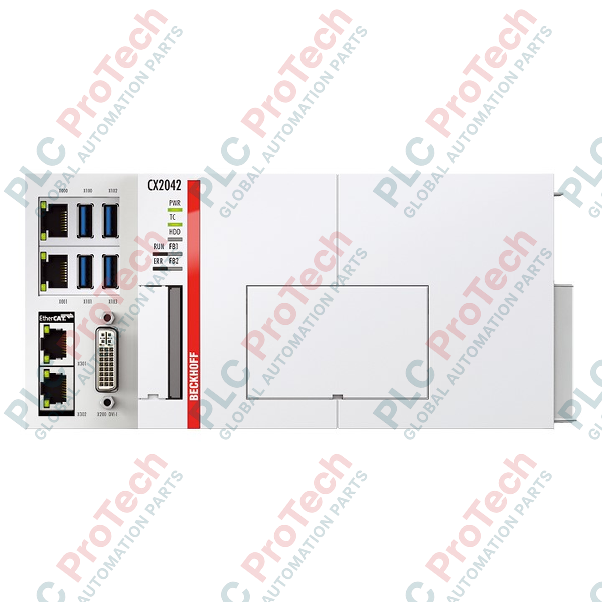
Serving as a highly resilient processing hub for modular control architectures, the Beckhoff CX2042-N031-0004 basic CPU module handles complex PLC, motion control, and visualization tasks within industrial automation systems. This controller features an integrated N031 serial interface option, physically broken out via a 9-pin D-sub socket. Designed specifically for reliable point-to-point or bus topologies, the serial interface is factory-configured as a full duplex end point with internal termination enabled. This unit facilitates seamless integration into existing serial bus networks while offering the computational performance of the CX2000 hardware platform.
Features
-
Modular Processing Unit: Engineered for direct integration into the modular CX2000 Embedded PC block system.
-
Integrated Serial Option: Built-in N031 physical interface slot saves backplane space by avoiding external serial modules.
-
Full Duplex End Point Configuration: Optimized for bidirectional, simultaneous transmit and receive operations.
-
Active Bus Termination: Internal termination resistor circuitry is active, preventing signal reflections without external network components.
-
Industrial Diagnostic LEDs: Built-in status indicators provide rapid, real-time diagnostic visibility of system and network performance.
Applications
-
Multi-Axis Motion Control: Coordinating complex high-speed positioning tasks via EtherCAT terminals.
-
Legacy System Integration: Linking modern control architectures directly to legacy sensors or readouts requiring RS422 protocol.
-
Enclosed Control Cabinets: Heavy-duty manufacturing environments requiring localized high-performance computing on standard DIN rails.
-
Distributed SCADA Stations: Localized data processing and protocol translation on remote facility networks.
Technical Specifications
| Parameter |
Specification Value |
| Manufacturer |
Beckhoff Automation |
| Model Number |
CX2042-N031-0004 |
| Product Type |
Basic CPU Module |
| Interface Type |
RS422 (N031 option) |
| Connector Type |
9-pin D-sub socket |
| Serial Configuration |
Full duplex end point |
| Bus Termination |
On (internally terminated) |
| Software Compatibility |
TwinCAT runtime environment |
| System Interface |
Direct backplane bus connection |
| Shipping Weight (Calculated) |
3.0 kg (6.61 lbs) |
| Country of Origin |
Germany |
Connections and Interfaces
| D-sub 9-Pin Number |
RS422 Full Duplex Function |
| Pin 2 |
RxD+ (Receive Data +) |
| Pin 3 |
TxD+ (Transmit Data +) |
| Pin 5 |
GND (Signal Ground) |
| Pin 7 |
RxD- (Receive Data -) |
| Pin 8 |
TxD- (Transmit Data -) |
Alternative Models & Compatibility
This controller is fully integrated into the CX2000 series ecosystem. If replacing a standard basic module or a module with an alternative interface such as the N030 (RS232) or N010 (DVI/USB), verify all physical communication wiring beforehand. Be aware that substituting this module with a non-terminated model (such as an open point-to-point interface) will require external 120-ohm termination blocks to match line impedance.
Application Pitfalls & Engineering Notes
Because this module utilizes the built-in "-0004" active termination option, it must only be placed at the physical ends of your RS422 communication segment. Do not connect this device in the middle of a multi-drop RS422 bus loop, as the internal active termination will cause line reflections, signal degradation, and packet loss. Maintain proper spacing around the active fan cartridge of the CX2042 CPU to prevent thermal throttling inside high-density control panels.
Commissioning & Wiring Tips
When configuring communications within the TwinCAT System Manager, assign the N031 option interface directly to your virtual COM port or map the register bytes directly to your PLC task. Always use twisted-pair, double-shielded copper cabling for the RS422 lines to prevent electromagnetic interference from surrounding variable frequency drives and high-voltage contactors. The shield should be terminated cleanly to the functional earth ground rail at only one end of the segment.
Installation Guidelines
CRITICAL WARNING: Completely de-energize the entire control system cabinet before physical assembly, disassembly, or bus coupling. Confirm all residual charges have completely dissipated before handling the system bus contacts. Failure to do so can result in electrical shock, backplane bus damage, or erratic controller firmware corruption.
1
Mount the CPU module securely on a standard horizontal 35mm DIN rail (EN 60715) with the air vents clear of physical obstructions.
2
Align the side bus connectors with adjacent power modules or I/O terminals, sliding them firmly together until they click into lock.
3
Connect the pre-assembled RS422 communication cable to the D-sub 9 socket, fastening the retention screws on both sides to prevent loose contacts.
4
Apply DC control power to verify the status indicators. Initiate the system within TwinCAT for logical configuration.