Product Overview
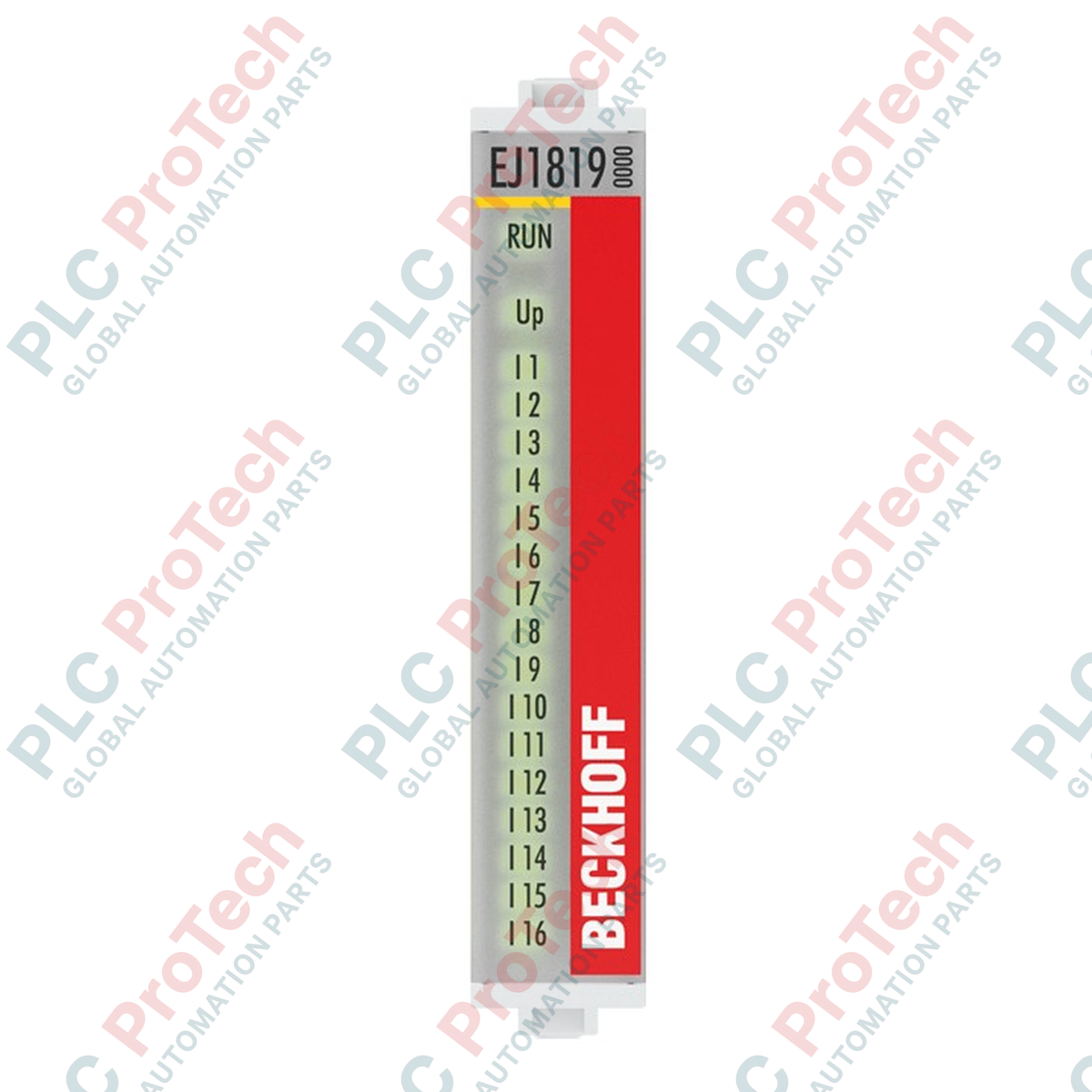
The EJ1819 (EJ1819) is a high-density EtherCAT plug-in module designed for large-scale manufacturing environments where space-saving and rapid assembly are paramount. Featuring 16 digital inputs in a compact form factor, this module is specifically engineered for the EJ series signal distribution board system, which replaces traditional point-to-point wiring with a standardized PCB-based connection level. In high-speed packaging, electronics assembly, and complex robotic cells, the EJ1819 significantly reduces the risk of wiring errors and minimizes the cabinet footprint. Its ultra-fast 10 microsecond input filter ensures precise signal acquisition for time-critical processes, making it a cornerstone for high-performance machine control and reduced system integration time.
Technical Configuration
The EJ1819 operates as a standard 24 VDC digital input interface, conforming to EN 61131-2, type 1/3 specifications. Its architecture is optimized for high-density I/O density, utilizing a plug-in design that connects directly to an application-specific Signal Distribution Board via a standardized connector. The module provides 16 channels of data, each drawing a typical input current of 3 mA. Signal integrity is maintained through 500 V electrical isolation between the E-bus and the field potential. Despite the high channel count, the module maintains a low power profile with a typical E-bus current consumption of 80 mA. The absence of Distributed Clocks (DC) is compensated by the module's high-speed internal processing and extremely low filter latency, suitable for rapid-fire sensor feedback.
Technical Specifications
| Feature |
Specification |
| Model |
EJ1819 |
| Brand |
BECKHOFF |
| Module Type |
EtherCAT Plug-in Module (Digital Input) |
| Number of Channels |
16 |
| Nominal Voltage |
24 VDC (-15 percent / +20 percent) |
| Signal Voltage "0" |
-3 to +5 V (EN 61131-2, type 1/3) |
| Signal Voltage "1" |
11 to 30 V (EN 61131-2, type 3) |
| Input Filter |
typ. 10 microseconds |
| E-bus Current Consumption |
typ. 80 mA |
| Electrical Isolation |
500 V (E-bus / field potential) |
| Operating Temperature |
-25 to +60 deg C |
| Weight |
approx. 30 g |
| Shipping Weight |
2.0 kg |
| Protection Rating |
IP20 |
Technical FAQs
How does the EJ1819 differ from the EL1819 terminal?
The EJ1819 provides the same 16-channel digital input functionality as the EL1819 but uses a plug-in housing designed for Signal Distribution Boards. While the EL series uses spring-loaded terminals for individual wires, the EJ series uses a multi-pin connector on the rear for mass-interconnect PCB mounting.
What are the benefits of the 10 microsecond input filter?
The 10 microsecond filter is significantly faster than standard industrial filters (often 3 ms). This allows the controller to detect extremely short pulses or high-frequency transitions from sensors, which is essential for high-speed counting or precision positioning tasks in automated assembly.
Can the EJ1819 be used in high-vibration environments?
Yes, the EJ1819 conforms to EN 60068-2-6 and EN 60068-2-27 standards. When properly seated on a Signal Distribution Board and secured, the plug-in design offers superior mechanical stability compared to traditional DIN rail terminals in high-vibration machinery.
Is it possible to mix EJ modules with different voltage levels on the same board?
This depends entirely on the design of your specific Signal Distribution Board. The EJ1819 requires a 24 VDC field potential. Ensure your PCB layout correctly segregates power planes if using modules with different voltage requirements.
Engineering & Installation Guide
-
PCB Landing Pattern & Alignment: When designing the Signal Distribution Board, ensure strict adherence to the Beckhoff EJ series connector footprint. Misalignment during the "plug-in" phase can lead to bent pins. Always use the mechanical coding pins to ensure the module is oriented correctly before applying downward pressure.
-
Heat Dissipation in High-Density Clusters: While a single EJ1819 consumes only 80 mA, a board populated with dozens of modules can generate significant localized heat. Maintain a minimum clearance as specified in the documentation and ensure the installation position allows for natural or forced convection to keep the ambient temperature below 60 deg C.
-
Field Potential Grounding: To achieve the rated 500 V electrical isolation and EMC immunity (EN 61000-6-2), ensure that the field potential ground (0V) on your distribution board is cleanly separated from the E-bus logic ground. Use wide traces or power planes on the PCB to minimize impedance and noise for the 16 signal channels.