Description
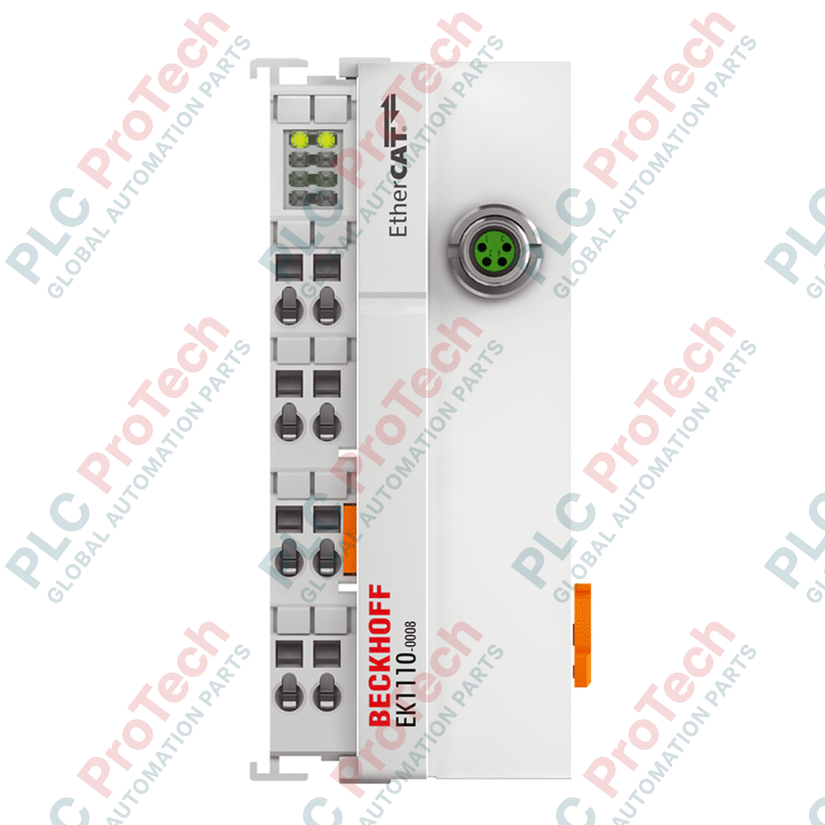
Integrating directly into the modular terminal block, the Beckhoff EK1110-0008 converts internal E-bus signals into standard 100BASE-TX Ethernet physical layers, allowing standard EtherCAT segments to be extended via industrial M8 cabling. This module enables the seamless coupling of distant EtherCAT terminals, drive systems, or additional field devices directly within the network architecture. Since it extracts its operating power directly from the E-bus, the Beckhoff EK1110-0008 requires no external auxiliary power supplies, streamlining panel layouts and reducing installation complexity.
Key Features
-
Signal Conversion: Transports E-bus backplane signals directly into a 100BASE-TX Ethernet format.
-
M8 Connectivity: Features a rugged, shielded, screw-type M8 port optimized for harsh environments.
-
Bus-Powered: Operates entirely on the 130 mA typical current supplied by the system E-bus.
-
High Isolation: Rated for 500 V electrical isolation between the supply voltage and Ethernet lines.
-
Zero-Configuration: Functions as a transparent network component requiring no software-based address configuration.
Applications
- Distributed machine control setups requiring flexible, IP20-rated M8 Ethernet patch connections.
- Multi-panel industrial systems requiring noise-isolated control signals across physical cabinet boundaries.
- Integration of specialized industrial sensors, linear encoders, and drive units into the primary EtherCAT network.
Technical Specifications
| Parameter |
Specification Value |
| Manufacturer |
Beckhoff |
| Model/Article Number |
EK1110-0008 |
| Interface Type |
1 x M8, shielded, screw-type |
| Data Transfer Medium |
Ethernet/EtherCAT cable (minimum Category 5), shielded |
| Power Supply Source |
Derived from the standard E-bus |
| Current Consumption (E-bus) |
130 mA typical |
| Electrical Isolation |
500 V (Supply voltage / Ethernet) |
| Operating Temperature |
-25 to +60 degC |
| Storage Temperature |
-40 to +85 degC |
| Relative Humidity |
95%, non-condensing |
| Protection Rating |
IP20 |
| Ex-Marking |
II 3 G Ex nA IIC T4 Gc |
| Standards & Approvals |
CE, UL, ATEX |
| Solid Wire Connection Range |
0.08 to 2.5 mm² (AWG 28 to 14) |
| Stranded Wire Connection Range |
0.08 to 2.5 mm² (AWG 28 to 14) |
| Ferrule Connection Range |
0.14 to 1.5 mm² (AWG 26 to 16) |
| Housing Material |
Polycarbonate (compact terminal form-factor) |
| Dimensions (W x H x D) |
44 mm x 100 mm x 68 mm |
| Net Weight |
50 g |
| Shipping Weight (Calculated) |
2.0 kg |
| Country of Origin |
Germany |
Connections and Interfaces
| M8 Connector Pin |
Signal Assignment |
Description |
| Pin 1 |
Tx + |
Transmit Data Positive |
| Pin 2 |
Rx + |
Receive Data Positive |
| Pin 3 |
Tx - |
Transmit Data Negative |
| Pin 4 |
Rx - |
Receive Data Negative |
Empirical Engineering Insights
Alternative Models & Compatibility
The standard EK1110 variant features an RJ45 socket, whereas the EK1110-0008 features a 4-pin M8 socket. This M8 variant is specifically designed for environments demanding high mechanical security or integration with pre-molded M8 industrial cables. In situations where RJ45 cabling is already deployed, standard EtherCAT patch cords with an M8-to-RJ45 adapter configuration must be specified to maintain shielding integrity.
Application Pitfalls & Engineering Notes
Since the module consumes 130 mA directly from the E-bus, system engineers must verify that the preceding EtherCAT Coupler (e.g., EK1100) or power supply terminal (e.g., EL9400) provides sufficient current capability. Adding too many downstream extensions without auxiliary E-bus power feed terminals will drop the E-bus voltage, resulting in intermittent network drops and localized communication errors.
Commissioning & Wiring Tips
When connecting M8 connectors, ensure they are torqued precisely to the manufacturer's recommended torque of 0.4 Nm. Over-tightening can fracture the internal polycarbonate housing mounts, while under-tightening will compromise the shield contact, making the downstream EtherCAT trunk susceptible to high-frequency electromagnetic interference (EMI) from adjacent variable speed drives.
Installation Guidelines
CRITICAL WARNING: ELECTRICAL HAZARD
De-energize all field power supplies and backplane voltage rails before attempting to install, insert, or extract the Beckhoff EK1110-0008 module. Failure to fully power down the control rail may cause contact arcing, damaging the internal E-bus circuitry and corrupting the physical TwinCAT hardware configurations.
1
Disconnect all active system power and verify that the 35 mm DIN rail (EN 60715) is correctly grounded to the central panel star-ground points.
2
Position the module directly adjacent to the existing terminal stack and slide it onto the rail until the side-by-side slot-and-key connection locks securely.
3
Attach the shielded M8 industrial Ethernet cable and screw down the retaining ring to complete the ground path across the connector shell.