Product Overview
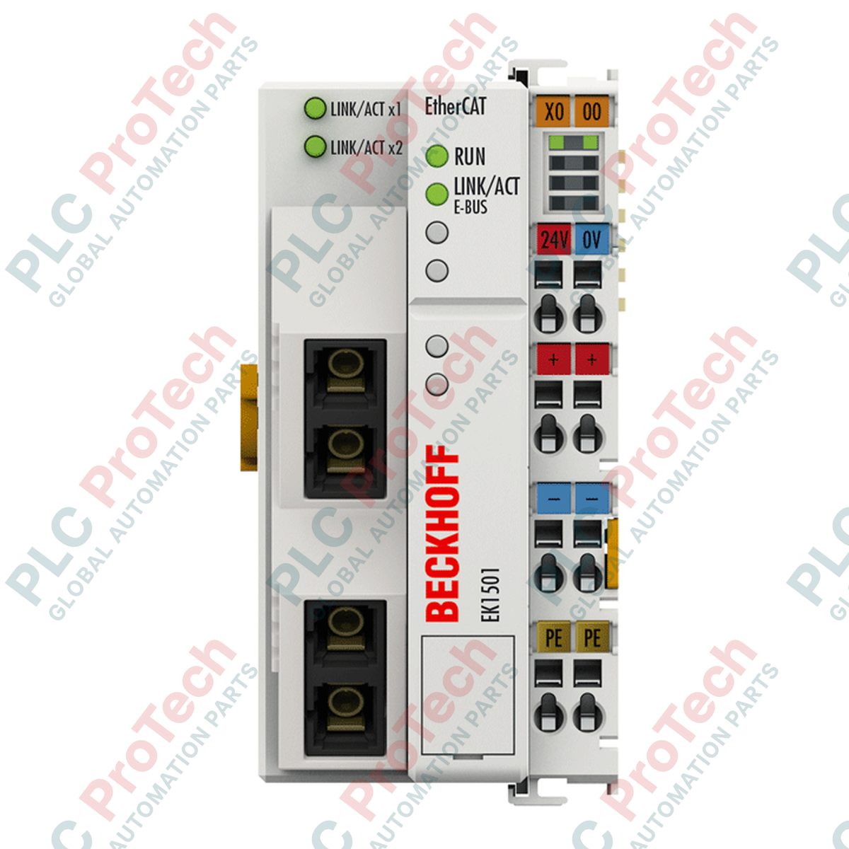
The EK1501 (EK1501) is a high-performance EtherCAT Coupler designed to bridge 100BASE-FX fiber optic networks with standard EtherCAT Terminals (ELxxxx). Engineered for large-scale industrial topologies, such as wind farms, sprawling logistics centers, and EMI-heavy manufacturing plants, this module utilizes multi-mode glass fiber (50/125 micrometers) to extend station distances up to 2000 m. The EK1501 features an integrated ID switch, allowing for the configuration of up to 4096 unique identities, which is essential for modular machine designs where the network topology may change dynamically. By utilizing fiber optic technology, it provides total immunity to electromagnetic interference and eliminates potential differences between distant segments, ensuring a robust and stable control architecture.
Technical Configuration
The EK1501 serves as the head station for an EtherCAT Terminal block, converting the optical 100BASE-FX signals to the internal E-bus signal representation. It features two SC Duplex interfaces, enabling flexible line or tree topologies. The hardware is equipped with three decimal rotary ID switches, enabling the assignment of a permanent "Hot Connect" group ID directly on the device. With an E-bus current supply of 2000 mA, the coupler can power a significant number of downstream I/O modules without requiring additional power feed terminals. Its 1-microsecond internal delay ensures that the high-speed deterministic performance of the EtherCAT protocol is maintained across long-distance fiber links.
Technical Specifications
| Feature |
Specification |
| Model |
EK1501 |
| Brand |
BECKHOFF |
| Origin |
Germany |
| Data Transfer Medium |
Multi-mode glass fiber 50/125 micrometers (MM) |
| Max. Distance |
2000 m between stations |
| Bus Interface |
2 x SC Duplex |
| E-bus Current Supply |
2000 mA |
| Configurable IDs |
4096 (via rotary switch) |
| Power Supply |
24 VDC (-15 percent / +20 percent) |
| Data Transfer Rate |
100 Mbit/s |
| Dimensions (W x H x D) |
51 mm x 100 mm x 69 mm |
| Operating Temperature |
-25 to +60 deg C |
| Weight |
0.19 kg |
Technical FAQs
How is the ID switch utilized in a TwinCAT environment?
The rotary switches on the EK1501 allow the user to set a unique identification value (0-4095). When the "Check Identification" feature is enabled in TwinCAT, the master verifies this ID before starting communication, ensuring the correct physical module is in the correct logical position in modular machine applications.
What is the advantage of SC Duplex fiber connections over standard RJ45?
Fiber optic connections provide complete galvanical isolation and are immune to electrical noise (EMI/RFI). This makes the EK1501 ideal for environments with heavy welding equipment, large frequency drives, or where cable runs must pass between different buildings with varying ground potentials.
Can I mix copper and fiber optic segments in the same network?
Yes. You can use an EK1100 (copper) at the main controller and transition to the EK1501 (fiber) for a long-distance run, or vice versa, provided the media converters or couplers match the 100BASE-FX standard.
Engineering & Installation Guide
-
Fiber Optic Handling: Ensure the SC Duplex connectors are kept clean. Use lint-free wipes and specialized optical cleaning fluid before insertion. Even microscopic dust on the fiber face can cause significant signal attenuation or link failure over long distances.
-
Bending Radius: When installing the multimode fiber in cable trays or conduits, adhere strictly to the manufacturer's minimum bending radius. Excessive bending can cause "micro-bends" in the glass core, leading to permanent signal loss and intermittent "CRC Error" flags in the EtherCAT master.
-
Power Distribution: The EK1501 provides up to 2000 mA to the E-bus. If your attached ELxxxx terminals exceed this total current draw (sum of E-bus currents), you must insert an EL9400 or EL9410 power supply terminal into the stack to refresh the E-bus power.
-
Thermal Management: When mounting on a 35 mm DIN rail, ensure vertical orientation to optimize airflow through the ventilation slots. If installed in an ATEX Zone 2 environment, ensure the enclosure meets the required IP54 rating as per EN 60079-15.