Description
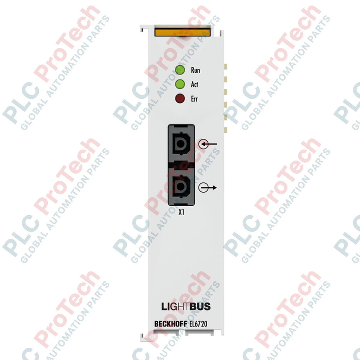
Directly integrating legacy Lightbus networks into high-speed EtherCAT architectures, the Beckhoff EL6720 serves as a deterministic 1-channel communication interface. Operating as a Lightbus master terminal, this unit facilitates high-speed optical fiber communications, ensuring complete immunity to electromagnetic interference in harsh electrical environments. The Beckhoff EL6720 provides an direct gateway between TwinCAT-based EtherCAT control systems and existing Lightbus field devices, handling up to 254 nodes with precise synchronization and minimal latency.
Features
-
High-Speed Communication: Sustained data transfer rates of 2.5 Mbaud over fiber-optic networks.
-
Broad Node Capacity: Supports connection of up to 254 fieldbus devices and a maximum of 65,280 I/O points.
-
Optical Noise Immunity: Dual-channel fiber-optic standard connectors minimize electrical noise propagation.
-
Deterministic Processing: Utilizes three priority-controlled logical communication channels for optimized task execution.
-
Real-Time Status Monitoring: Integrated diagnostic layout featuring 3 front-panel LEDs for instant hardware and network status verification.
Applications
- Retrofitting and upgrading legacy Beckhoff Lightbus machinery to modern EtherCAT architectures.
- Heavy industrial environments requiring high optical isolation from electromagnetic noise.
- Distributed I/O networks spanning long distances inside high-voltage switchgear cabinets.
Technical Specifications
| Parameter |
Specification Value |
| Manufacturer |
Beckhoff |
| Model / SKU |
EL6720 |
| Technology |
Lightbus master terminal |
| Number of Fieldbus Channels |
1 |
| Data Transfer Rate |
2.5 Mbaud |
| Interfaces |
2 x fiber-optic standard connector Z1000 (plastic fiber) or Z1010 (HCS fiber) |
| Current Consumption E-bus |
Typically 240 mA |
| Hardware Diagnostics |
3 LEDs |
| Housing Dimensions (W x H x D) |
24 mm x 100 mm x 52 mm |
| Operating Temperature |
0 to +55 degC |
| Storage Temperature |
-25 to +85 degC |
| Relative Humidity |
95 %, non-condensing |
| Vibration / Shock Resistance |
Conforms to EN 60068-2-6 / EN 60068-2-27 |
| Protection Rating / Position |
IP20 / Variable |
| Ex Marking |
II 3 G Ex nA IIC T4 Gc |
| Net Weight |
70 g |
| Shipping Weight (Calculated) |
2.0 kg |
Connections and Interfaces
| Connector Type |
Function Assignment |
| Tx Optical Port |
Fiber-optic Lightbus Transmitter Output (Z1000 / Z1010 connection) |
| Rx Optical Port |
Fiber-optic Lightbus Receiver Input (Z1000 / Z1010 connection) |
Empirical Engineering Insights
Alternative Models & Compatibility
The EL6720 replaces legacy PCI master cards (such as the FC2001) by shifting the Lightbus controller functionality onto the standard DIN rail. TwinCAT 2.11 (or higher) and all versions of TwinCAT 3 fully support configuration of this module. Hardware topology requires a closed-ring configuration; ensure that there are no gaps in the optical line.
Application Pitfalls & Engineering Notes
Do not exceed a minimum bend radius of 25 mm for standard plastic optical fiber (POF) lines. Tight bends degrade light intensity, causing intermittent framing errors or complete "Ring Interrupted" diagnostic states. Always verify the quality of POF termination cuts; rough or jagged cuts degrade transmission signal margins dramatically.
Commissioning & Wiring Tips
During initial commissioning in TwinCAT System Manager, utilize the "Scan" function under the EtherCAT Master device. If the EL6720 is correctly initialized but cannot discover Lightbus devices downstream, verify that the Tx and Rx fibers have not been crossed at the terminal connector interface.
Installation Guidelines
CRITICAL WARNING: Completely de-energize the entire Bus Terminal assembly and ensure the system is locked out before snapping the module onto or removing it from the DIN rail. Hot-plugging or live insertion of EtherCAT terminals can degrade internal E-bus spring contacts and trigger fieldbus faults across the entire network node.
1
Align the EL6720 with the DIN rail guide and push firmly until the mounting latch clicks securely into place.
2
Slide adjacent terminals together, ensuring that the lateral tongue-and-groove joint is locked to guarantee continuous electrical contact of the internal E-bus.
3
Insert clean, perpendicular-cut Z1000 or Z1010 fiber cables into the designated optical ports until locked.