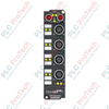
Description
Designed for direct physical deployment in harsh field environments, the Beckhoff EPP5151-0002 interface box enables high-speed acquisition of differential RS422 and single-ended incremental encoder signals over EtherCAT P. By integrating data and power into a single, specialized M8 P-coded connection, this module minimizes cabling overhead while providing IP67-rated protection against moisture, dust, and mechanical stress. The device features a 32/16-bit binary counter, built-in latch functionality, and microsecond-level synchronization via Distributed Clocks, making it suitable for precise position tracking and speed measurement in decentralized automation topologies.
Features
-
Single-Cable Automation: Utilizes EtherCAT P technology to combine system/sensor voltage (Us) and peripheral voltage (Up) on a single M8 transmission line.
-
High-Frequency Acquisition: Supports limit frequencies up to 4 million increments per second (with 4-fold quadrature evaluation, corresponding to 1 MHz input frequency).
-
Flexible Signal Input: Accommodates differential RS422 signals as well as single-ended inputs.
-
Rugged Design: Housed in a polyamide (PA6) enclosure offering high vibration and shock resistance with IP65/66/67 protection ratings.
-
Distributed Clocks: Enhances system synchronization by aligning input captures with sub-microsecond precision across the EtherCAT network.
Applications
- Decentralized conveyor systems requiring real-time tracking of line speeds and packaging feeds.
- Heavy material handling and logistics machinery operating in highly contaminated or high-vibration zones.
- Rotary encoder interfacing for wind turbines, cranes, and outdoor machinery without protective junction boxes.
- Gantry positioning and tool alignment systems running on TwinCAT platforms.
Technical Specifications
| Parameter |
Specification |
| Manufacturer |
Beckhoff |
| Model/Article Number |
EPP5151-0002 |
| Bus Interface |
2 x M8 socket, shielded, screw type, P-coded (EtherCAT P) |
| Encoder Interface |
M12, screw type, 8-pin |
| Encoder Type |
Incremental, differential (RS422), single-ended configuration supported |
| Number of Channels |
1 |
| Counter Depth |
16-bit or 32-bit binary |
| Limit Frequency |
4 MHz (with 4-fold evaluation); 1 MHz input |
| Nominal System Voltage |
24 V DC (-15% / +20%) |
| Encoder Operating Voltage |
24 V DC, 0.5 A max (derived internally from Us supply) |
| Current Consumption from Us |
Typically 100 mA |
| Electrical Isolation |
500 V RMS |
| Operating Temperature Range |
0 to 55 degC |
| Storage Temperature Range |
-25 to 85 degC |
| IP Rating |
IP65 / IP66 / IP67 (conforms to EN 60529) |
| Enclosure Material |
Polyamide PA6 |
| Dimensions (W x H x D) |
30 mm x 126 mm x 26.5 mm |
| Physical Weight |
Approx. 165 g |
| Shipping Weight (Calculated) |
0.35 kg |
Connections and Interfaces
| M12 Encoder Pin |
Signal Assignment |
Functional Detail |
| Pin 1 |
Channel A+ |
Incremental Encoder Input A (Differential) |
| Pin 2 |
Channel B+ |
Incremental Encoder Input B (Differential) |
| Pin 3 |
Channel C+ |
Encoder Zero Pulse Latch Input (Differential) |
| Pin 4 |
Gate / Status Input |
Enables/disables counter via hardware input |
| Pin 5 |
+24 V DC (Us) |
Sensor/Encoder Power Supply Output (Max 0.5 A) |
| Pin 6 |
GND (Us) |
Reference potential for encoder supply |
| Pin 7 |
Shield / FE |
Functional Ground/Cable Shield Connection |
| Pin 8 |
Auxiliary Input |
Configurable binary input |
Empirical Engineering Insights
Alternative Models & Compatibility
The EPP5151-0002 belongs specifically to the EtherCAT P family. It is electrically incompatible with standard EtherCAT (EP5151-0002) couplers and hubs unless an EPP9022-0022 line topology coupler or EtherCAT-to-EtherCAT P junction is introduced upstream. Ensure that your configuration features an appropriate P-coded master port (e.g., EL9822 or EK1322) capable of supplying clean system (Us) and peripheral (Up) power.
Application Pitfalls & Engineering Notes
When deploying high-speed encoders over long cable lengths (exceeding 10 meters) with single-ended signaling, line capacitance can degrade signal integrity at high pulse rates. Under these conditions, differential RS422 mode must be chosen to maintain counter accuracy and prevent spurious pulse drops caused by common-mode noise. Ensure total load current from Us does not exceed the built-in 0.5 A current limiting threshold to avoid system shutdowns.
Commissioning & Wiring Tips
Always configure shielding correctly on the M12 connector. Do not rely solely on the thread mounting of the EPP housing for ground connection; run a low-impedance grounding wire directly from one of the module's 3.5 mm mounting holes to the machinery's common functional earth terminal (FE). Use TwinCAT 3 to perform a "Scan" operation in configuration mode to instantly load the XML description, and adjust parameter 8000 (CoE settings) to select 16-bit or 32-bit counter modes based on application requirements.
Installation Guidelines
CRITICAL WARNING
Disconnect all power sources supplying the EtherCAT P bus line before adding or removing the EPP5151-0002 module. Live hot-plugging on M8 P-coded interfaces under high capacitive loads can cause internal contact arcing and degrade the gold-plated pins of the interface.
1
Securely mount the EPP5151-0002 to a rigid, clean surface using two M3 screws through the 3.5 mm diameter fixing holes on the polyamide housing.
2
Connect the incoming EtherCAT P M8 cable (P-coded, typically marked green) to the "IN" port, ensuring the locking sleeve is screwed down hand-tight to preserve the IP67 seal.
3
Attach the M12 encoder connector to the dedicated sensor port. Avoid over-torqueing the metal collar (nominal torque should not exceed 0.6 Nm).
4
Ensure any unused ports are protected with watertight dummy caps to prevent dust and water intrusion.