System Infrastructure Overview
The Beckhoff KS9505 (KS9505) is a high-precision, stabilized 5 V DC power supply Bus Terminal module engineered within the pluggable KS series I/O framework. Deployed across automated control racks, high-density sensor networks, optical measurement systems, and precise instrumentation loops, this hardware module converts standard industrial power potentials into clean logic-level outputs. It filters out high-frequency electrical line interference from upstream industrial machinery, ensuring the power distributed across downstream expansion slices maintains exceptional voltage stability under varying mechanical loads.
Power Conversion Topology and Mechanical Profile
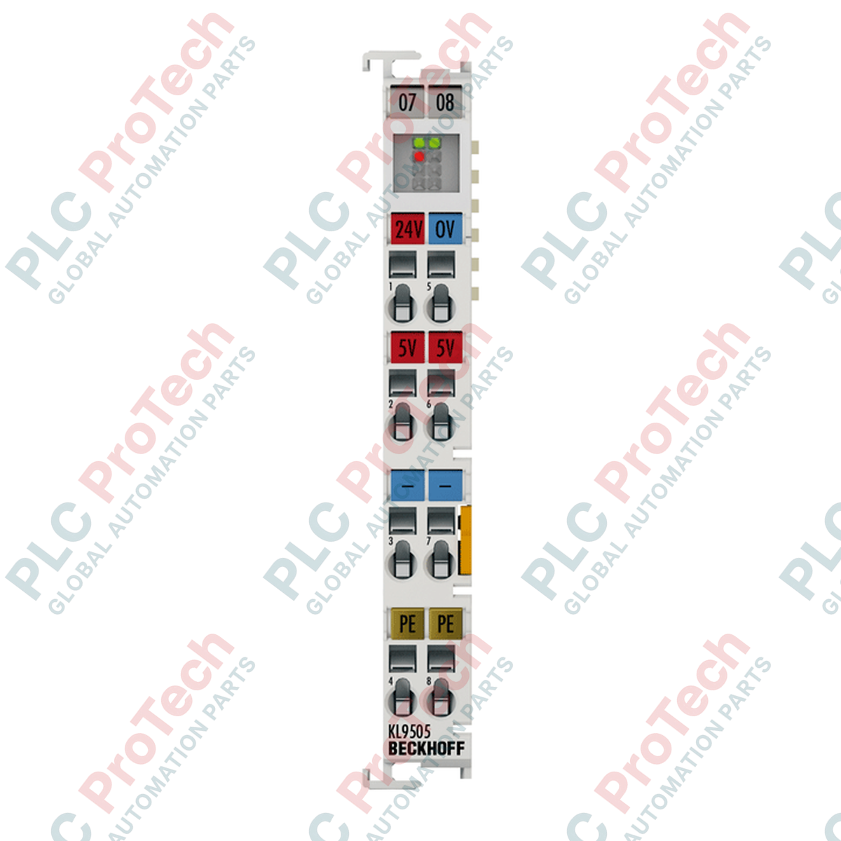
This 12 mm wide module accepts a standard 24 V DC input potential (-15% / +20%), down-stepping the voltage to a highly regulated 5 V DC output with a structural accuracy of $\pm 1\%$. Delivering a continuous current capacity of 0.5 A, the solid-state regulator features integrated short-circuit protection and limits residual output ripple to less than 5 mV to prevent signal jitter in highly sensitive internal logic cards. Housed in a durable polycarbonate shell with an IP20 rating, the KS9505 features a pluggable wiring level that allows the entire terminal block insert to be removed from the housing base during hot-swap field servicing without disconnecting individual field conductors.
Technical Performance Matrix
| System Parameter |
Functional Specification |
| Model Number |
KS9505 |
| Brand / Product Family |
Beckhoff Automation / Pluggable KS-Bus Terminal Series |
| Input Potential Threshold |
24 V DC (-15 % / +20 %) |
| Output Voltage Specification |
5 V DC $\pm 1\%$ (Highly stabilized performance) |
| Continuous Output Current |
0.5 A |
| Residual Voltage Ripple |
< 5 mV peak-to-peak |
| Short-Circuit Safeguard |
Yes (Integrated electronic recovery logic) |
| Diagnostic Indicators |
Integrated front faceplate overcurrent status LED |
| Power Contacts Current Load |
$I_{max}$: 10 A (Through-bus blade capacity) |
| Hazardous Area Approvals |
CE, UL, ATEX Zone 2 Rated |
| Ex Safety Marking |
II 3 G Ex nA IIC T4 Gc |
| Operating Temperature |
0 to +55 deg C (Non-condensing environment) |
| Storage Temperature |
-25 to +85 deg C |
| Physical Dimensions (W x H x L) |
12 mm x 100 mm x 68 mm |
| Net Hardware Weight |
0.065 kg |
| Shipping Gross Weight |
2.0 kg (Enclosed in shock-resistant packaging) |
Industrial Diagnostics and FAQs
What causes the front faceplate overcurrent LED to illuminate, and how does the module recover?
The overcurrent LED turns on when the downstream 5 V DC logic load exceeds the module's 0.5 A continuous current threshold, or if a short circuit occurs across the internal terminal bus distribution lines. When this fault triggers, the internal regulator limits its current output to protect the internal components. Once you locate and remove the faulty downstream I/O card or shorted wiring, the module automatically resets its voltage regulation circuit and clears the fault LED.
Does this module pass the primary 24 V DC input potential down the lateral rail power contacts?
Yes. The terminal block contains internal power blades rated for a maximum continuous current load of 10 A. The primary 24 V DC input potential applied to the front spring terminals lands on these lateral blade contacts, allowing it to pass down the rail stack to power adjacent standard I/O slices. At the same time, the module's internal circuitry taps into this 24 V DC line to generate the regulated 5 V DC logic potential.
What specific wiring benefits does the KS9505 model prefix offer over standard KM or KL modules?
The "KS" prefix indicates that the module features a two-piece pluggable wiring design level. Standard KL modules use fixed terminal blocks where the wires connect directly to the housing. On the KS9505, the spring-actuated terminal block can be detached from the module base as a single unit. This design allows maintenance technicians to replace a damaged or worn module without disconnecting and re-landing individual field wires, reducing down-time and preventing wiring errors.
Field Commissioning and Wiring Guidelines
-
Spring Actuation Conductor Insertion: Wire connections are managed using integrated spring clamps operated with a precision flat-blade screwdriver. Strip conductor insulation back exactly 9 to 10 mm. Insert the screwdriver tool into the release slot to open the internal spring gate, insert the bare solid or stranded wire (0.08 to 1.5 mm² / AWG 28 to 16) fully into the conductor path, and remove the tool to secure the connection.
-
ATEX Zone 2 Installation Criteria: Under the ATEX Ex nA IIC T4 Gc rating, this equipment is approved for deployment within Zone 2 hazardous areas. To maintain this rating, you must install the terminal stack inside an ATEX-certified industrial enclosure that provides a minimum ingress protection level of IP54. Never disconnect the pluggable wiring block or pull modules apart while the supply circuit is live unless the surrounding area is verified to be completely free of flammable gas concentrations.
-
DIN Rail Seating and Side Interlocking: Snap the housing vertically onto standard 35 mm TS35 DIN rails that comply with EN 60715 standards. Use the integrated locking mechanism to secure the module. Slide the unit sideways along the rail to engage the double slot-and-key side connections with adjacent terminals. Ensure the rail itself connects directly to the enclosure's main low-impedance ground bar to allow the module's internal filtering networks to dissipate high-frequency electromagnetic noise.