Description
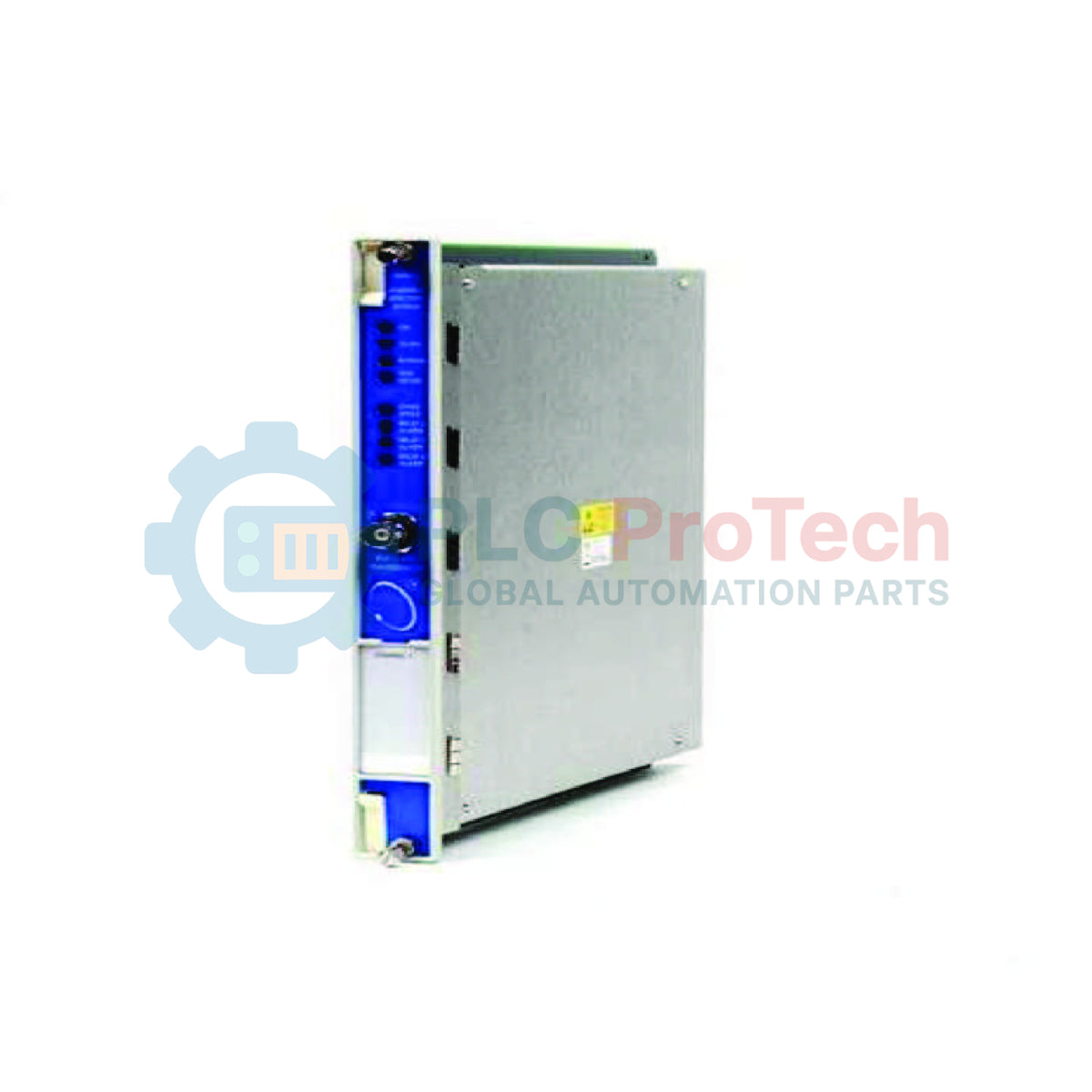
Executing continuous, online machinery protection, the Bently Nevada 176449-01 is a high-performance 3500/40M Proximitor Monitor designed for integration into the 3500 Series Machinery Protection System. This module accepts input signals from various proximity transducer systems, conditions these inputs to supply continuous vibration and position measurements, and compares the processed parameters against programmable alarm setpoints to trigger automatic machinery shutdown or alert operators of dynamic faults.
With its four-channel architecture, the monitor performs critical diagnostics including radial vibration, axial thrust position, eccentricity, and differential expansion. Operating in conjunction with the 3500/01 configuration software, each channel can be programmed independently, allowing diverse field instrumentation interfaces across a single module. Active status indicators and dedicated front-panel buffered output connections facilitate seamless integration into local control networks and external diagnostic machinery analyzers.
Features
-
Four-Channel Architecture: Enables concurrent monitoring of up to four independent proximity transducer inputs.
-
Programmable Configuration: Highly configurable channel types accommodate radial vibration, thrust position, differential expansion, or eccentricity.
-
Dynamic Signal Buffering: Front-panel coaxial coaxial connectors supply clean, buffered transducer outputs for portable diagnostic analyzers without signal degradation.
-
Comprehensive Alarming: Setpoints for Alert and Danger thresholds are configurable for each channel with selectable time delays.
-
System Diagnostics: Automatic internal self-tests continuously verify monitor integrity, transducer wiring connectivity, and OK status limits.
Applications
- Steam, gas, and hydro turbine shaft radial vibration and axial thrust monitoring.
- High-capacity centrifugal and axial compressor protection systems.
- Critical industrial pumps, fans, and blowers in heavy process industries.
- Gearbox shaft displacement diagnostics and structural casing vibration alignment.
Technical Specifications
| Parameter |
Specification |
| Manufacturer |
Bently Nevada |
| Model Number |
3500/40M (176449-01) |
| Input Channels |
4 channels, independent configuration |
| Compatible Transducers |
Bently Nevada 3300, 3300 XL, 7200, and non-standard proximity sensor systems |
| Signal Resolution |
24-bit A/D conversion |
| Buffered Outputs |
Front-panel coaxial connectors (impedance matched) |
| Power Consumption |
7.7 watts typical |
| Operating Temperature |
-30 to +65 degC (-22 to +150 Fahrenheit) |
| Country of Origin |
United States |
| Shipping Weight (Calculated) |
2.0 kg (4.4 lbs) |
| Package Dimensions (Calculated) |
26.0 x 24.5 x 5.0 cm |
Empirical Engineering Insights
Alternative Models & Compatibility
The 3500/40M is the high-density direct upgrade to legacy non-M versions. When upgrading, check your 3500 Rack Configuration Software version; the 3500/40M series requires software version 3.3 or higher. It is physically compatible with both standard and high-density 3500 series backplanes, but the appropriate I/O modules must match the corresponding internal backplane layout.
Application Pitfalls & Engineering Notes
When running extended field cable runs, verify the voltage drop. The monitor feeds direct power (-24 VDC) to the Proximitor sensors. Excessively long or poorly shielded extension cables can attenuate the AC dynamic component, leading to signal distortion or false OK errors. Ground loops are a common failure point during commissioning; shield integrity must terminate cleanly at the 3500 rack ground bar and remain isolated at the sensor housing.
Commissioning & Wiring Tips
Before powering up the unit, ensure the scale factor matches your proximity transducer system (typically 200 mV/mil or 7.87 V/mm for standard 8mm systems). Use the front-panel coaxial connectors to monitor the DC gap voltage during the sensor positioning stage. Adjust the probe depth until the gap voltage reads within the -9.0 to -11.0 VDC range (representing the center of the linear operating range) before tightening the probe bracket.
Installation Guidelines
CRITICAL WARNING: De-energize all power sources supplying the 3500 rack and associated field instrumentation before executing card insertion or extraction. Live hot-swapping under active process control can result in false ESD trip signals or cause immediate damage to sensitive internal electronic components.
1
Align the module carefully with the guides of the selected chassis slot within the 3500 rack, ensuring correct keying orientation.
2
Slide the module firmly into the rack until the rear connectors interface securely with the backplane connectors.
3
Tighten the two integrated captive thumbscrews on the front faceplate to lock the module physically in place.
4
Verify field wiring contacts on the rear I/O block against your specific loop diagram before energizing system power.