Description
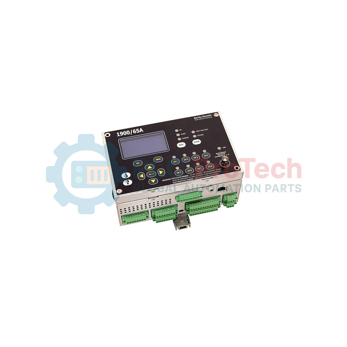
Monitoring and safeguarding critical midsize machinery is the core function of the Bently Nevada 1900/65A-00-01-00-00-00. This self-contained, four-channel General Purpose Equipment Monitor provides continuous monitoring of vibration, temperature, speed, or process variables. Designed to operate as a standalone protection system or integrate seamlessly into broader plant monitoring architectures, this model is equipped with an integrated, factory-attached front display. This setup enables localized, real-time value tracking and status diagnostics without requiring external interface panels. Running on a standard low-voltage DC power configuration, this robust industrial monitor offers cost-effective, high-reliability machinery protection for applications where larger, rack-mounted protection systems are not economically or physically practical.
Features
- Four fully configurable input channels supporting proximity probes, velocity transducers, accelerometers, or standard static process signals.
- Integrated front-panel display offering real-time diagnostic reporting, channel values, and active alarm statuses.
- Four configurable SPDT relay outputs dedicated to Alert and Danger setpoints, facilitating automatic hazard mitigation or trip sequences.
- Four buffered transducer output connections providing clean, raw analog signals for direct analysis using portable diagnostic equipment.
- Flexible parameter configuration via dedicated utility software to optimize bandpass filters, scale factors, and relay logic.
Applications
-
Rotating Machinery Protection: Continuous vibration and temperature monitoring on industrial fans, blowers, and exhausters.
-
Fluid Handling Equipment: Early warning and trip protection for centrifugal and positive-displacement pumps.
-
Plant Utility Support: Monitoring of small air compressors, cooling tower gearboxes, and auxiliary generators.
-
Stand-Alone Enclosures: Localized protection loops where a central 3500 series monitoring rack is physically or financially impractical.
Ordering Information
The model number 1900/65A-00-01-00-00-00 specifies a precise hardware build configuration breakdown as detailed below:
| Option Field |
Option Code |
Selection Details |
| Power Option |
00 |
18 to 36 Vdc (Low-voltage DC supply) |
| Display Option |
01 |
Attached Display (Integrated front panel interface) |
| Mounting Option |
00 |
Panel Mount (Standard cutout installation) |
| Approvals Option |
00 |
None (Standard/No hazardous area certifications) |
| Communications Option |
00 |
None (No Modbus communications card installed) |
Technical Specifications
| Parameter Specification |
Value / Details |
| Manufacturer |
Bently Nevada |
| Model Series |
1900 Series |
| Input Channels |
4 configurable transducer inputs (Vibration, Acceleration, Velocity, Temperature, or Process) |
| Auxiliary Inputs |
Dedicated Speed/Keyphasor input channel |
| Input Supply Voltage |
18 to 36 Vdc (3.0 Watts nominal power consumption) |
| Display Unit |
Integrated liquid crystal display with status LED diagnostics |
| Relay Contact Rating |
SPDT contacts, rated for 5 A at 250 Vac or 30 Vdc (resistive load) |
| Operating Temperature |
-20 to +70 degC (-4 to +158 Fahrenheit) |
| Humidity Range |
Up to 95% relative humidity, non-condensing |
| Country of Origin |
United States |
| Shipping Weight (Calculated) |
2.0 kg |
| Package Dimensions (Calculated) |
25.0 x 20.0 x 15.0 cm |
Connections and Interfaces
| Terminal / Connection Group |
Signal / Pin Assignment |
Functional Description |
| Power Terminals |
+V / -V / GND |
Primary 18 to 36 Vdc power connection with frame ground |
| Transducer Inputs (Ch 1-4) |
PWR / SIG / COM |
Supplies loop power to sensor and receives incoming dynamic/static signals |
| Keyphasor Input |
KPH PWR / SIG / COM |
Dedicated magnetic pickup or proximity probe speed input |
| Relay Terminals (Alert/Danger) |
NO / NC / COM |
Dry contacts for alarm trip routing to emergency shutdown systems |
| Buffered Outputs |
Coaxial BNC Jacks |
Four independent, non-isolated raw analog output signals |
Empirical Engineering Insights
Alternative Models & Compatibility
This hardware unit serves as a functional and physical direct replacement for older, non-"A" suffix versions of the 1900/65 monitor. Configuration files can be exported from legacy models and imported using the 1900 Configuration Software; however, firmware versions must be verified for compatibility before commissioning to ensure equivalent register mappings.
Application Pitfalls & Engineering Notes
Since this hardware build features Option E: 00 (No Communications), it does not support remote SCADA querying via Modbus RTU or Modbus TCP. For installations requiring direct DCS communication, raw analog signals or hardwired relay trips must be utilized. Alternatively, the hardware must be upgraded or specified with the Option E: 01 communications module.
Commissioning & Wiring Tips
When connecting portable vibration analyzers to the front-panel coaxial buffered outputs, ensure your diagnostic analyzer is either battery-operated or optically isolated. This configuration prevents ground loop currents from injecting noise into the sensitive active-monitoring loops of the system.
Installation Guidelines
CRITICAL WARNING: De-energize all primary and auxiliary power sources before installing, removing, or wiring the monitor. Verify that no hazardous explosive atmosphere is present at the installation site prior to opening terminal boxes or adjusting wiring pathways.
-
1
Prepare the physical panel cutout matching the exact mechanical dimensions specified for the panel-mount frame of the 1900/65A. Insert the unit and tighten the mounting brackets evenly to prevent gasket deformation.
-
2
Route the transducer cabling through dedicated, grounded metallic conduits. Terminate the shields strictly at the instrument side to prevent ground loop noise interference.
-
3
Wire the 18 to 36 Vdc power supply to the designated terminals. Verify correct polarity before applying power to prevent internal fuse trip events.
-
4
Connect to the monitor serial port using a PC running the 1900 Configuration Software to calibrate sensors, define trip delay times, and verify active relay configurations.