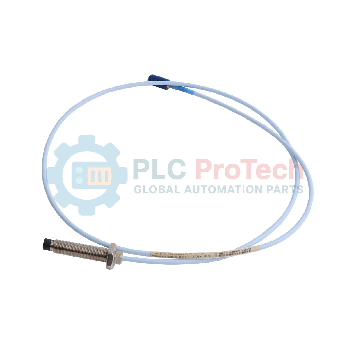
Description
Optimized for critical machinery protection, the Bently Nevada 330103-00-07-10-02-CN provides precise non-contact eddy current displacement measurements in demanding industrial environments. As a core component of the 3300 XL 8 mm Proximity Transducer System, this probe is engineered to continuously monitor shaft vibration, axial position, and oil-film dynamic behavior on rotating machinery. Built with a high-durability Polyphenylene Sulfide (PPS) tip and an AISI 303/304 stainless steel threaded body, it resists extreme mechanical stress and chemical exposure while delivering excellent thermal stability and performance repeatability.
Features
-
Fully Threaded Case: 0 mm unthreaded length option ensures rigid mounting and maximum thread engagement.
-
Engineered Tip Material: Polyphenylene sulfide (PPS) tip resists chemical degradation, moisture absorption, and thermal warping.
-
Stainless Steel Construction: AISI 303/304 stainless steel case offers robust mechanical protection and atmospheric corrosion resistance.
-
High-Reliability Connector: Miniature coaxial ClickLoc connector maintains a secure, vibration-resistant electrical contact with standard coaxial cables.
-
Integrated Pressure Seal: Internal Viton O-ring seals differential pressure between the probe tip and case assembly.
Applications
- Steam, gas, and hydro turbine shaft vibration and axial position monitoring.
- Centrifugal compressor radial dynamic motion and thrust bearing wear tracking.
- Industrial gearbox high-speed shaft runout and oil film thickness analysis.
- Heavy-duty utility pump and cooling fan bearing housing relative vibration measurement.
Technical Specifications
| Parameter |
Specification |
| Manufacturer |
Bently Nevada |
| Model / Order Code |
330103-00-07-10-02-CN |
| Product Series |
3300 XL 8 mm Proximity Transducer System |
| Thread Size |
3/8-24 UNF-2A (English Thread) |
| Unthreaded Length |
0 mm |
| Overall Case Length |
70 mm |
| Total Cable Length |
1.0 meter (3.3 feet) |
| Connector Type |
Miniature coaxial ClickLoc connector, standard cable |
| Probe Tip Material |
Polyphenylene sulfide (PPS) |
| Probe Case Material |
AISI 303 or 304 Stainless Steel (SST) |
| Sealing Mechanism |
Viton O-ring |
| Agency Approvals |
CN (Country-specific hazardous area approvals) |
| Net Weight |
0.323 kg |
| Shipping Weight (Calculated) |
1.30 kg |
| Country of Origin |
United States |
Connections and Interfaces
| Connector Interface |
Signal / Pin Assignment |
Electrical Description |
| ClickLoc Center Pin |
RF Signal Output |
Carries the high-frequency RF signal modulated by proximity to the target. |
| ClickLoc Outer Shield |
Signal Ground / Shield |
Provides reference ground and shielding from electrostatic and electromagnetic noise. |
Empirical Engineering Insights
Alternative Models & Compatibility: The 330103 series probe operates natively with 3300 XL Proximitor Sensors (such as the 330180-series). When upgrading legacy (non-XL) 3300 8 mm probe setups, always verify the Proximitor sensor calibration and matched system electrical length (5-meter or 9-meter configurations) to avoid severe scale-factor errors.
Application Pitfalls & Engineering Notes: Because this specific option features 0 mm of unthreaded length, the probe is fully threaded up to the case transition. When threading this unit into machine housings, do not exceed the recommended mounting torque of 33.9 N-m (300 in-lb) to prevent structural deformation of the stainless steel case or damage to the internal Viton sealing ring. The PPS tip is resilient against chemicals but brittle under direct physical impacts; ensure target dynamic runout never makes physical contact with the probe tip.
Commissioning & Wiring Tips: Ensure the ClickLoc connectors are completely clean and dry before mating. Moisture or particulate ingress inside the coaxial joint will degrade signal impedance and distort the voltage-to-gap calibration. For robust wet-environment installations, wrap the mated ClickLoc joint with self-fusing silicone tape (such as Bently Nevada connector silicone tape) to isolate the connection from lube oil and water vapor.
Installation Guidelines
CRITICAL WARNING
De-energize the monitored machinery and lockout all power sources before inserting or adjusting the proximity probe. Static charge build-up on the shaft or coaxial cable can damage sensitive Proximitor inputs. Ground yourself and use ESD-safe protocols during installation.
1
Establish Physical Gap: Carefully thread the probe into the mounting bracket or machine housing until the tip gently touches the target shaft. Note the position, then back the probe out to achieve the desired voltage offset (typically 1.27 mm or 50 mils gap for mid-range calibration).
2
Tighten the Locknut: Holding the probe body stationary with a backup wrench, torque the locknut to secure the probe in place. Re-verify the physical gap voltage at the Proximitor test points to ensure the probe did not rotate or shift during tightening.
3
Route Cable with Minimum Bend: Route the 1.0-meter coaxial cable back to the junction box or Proximitor location, ensuring the cable maintains a minimum bend radius of 25.4 mm (1.0 inch). Avoid clamping the cable too tightly, as this can compress the internal dialectric and shift electrical characteristics.