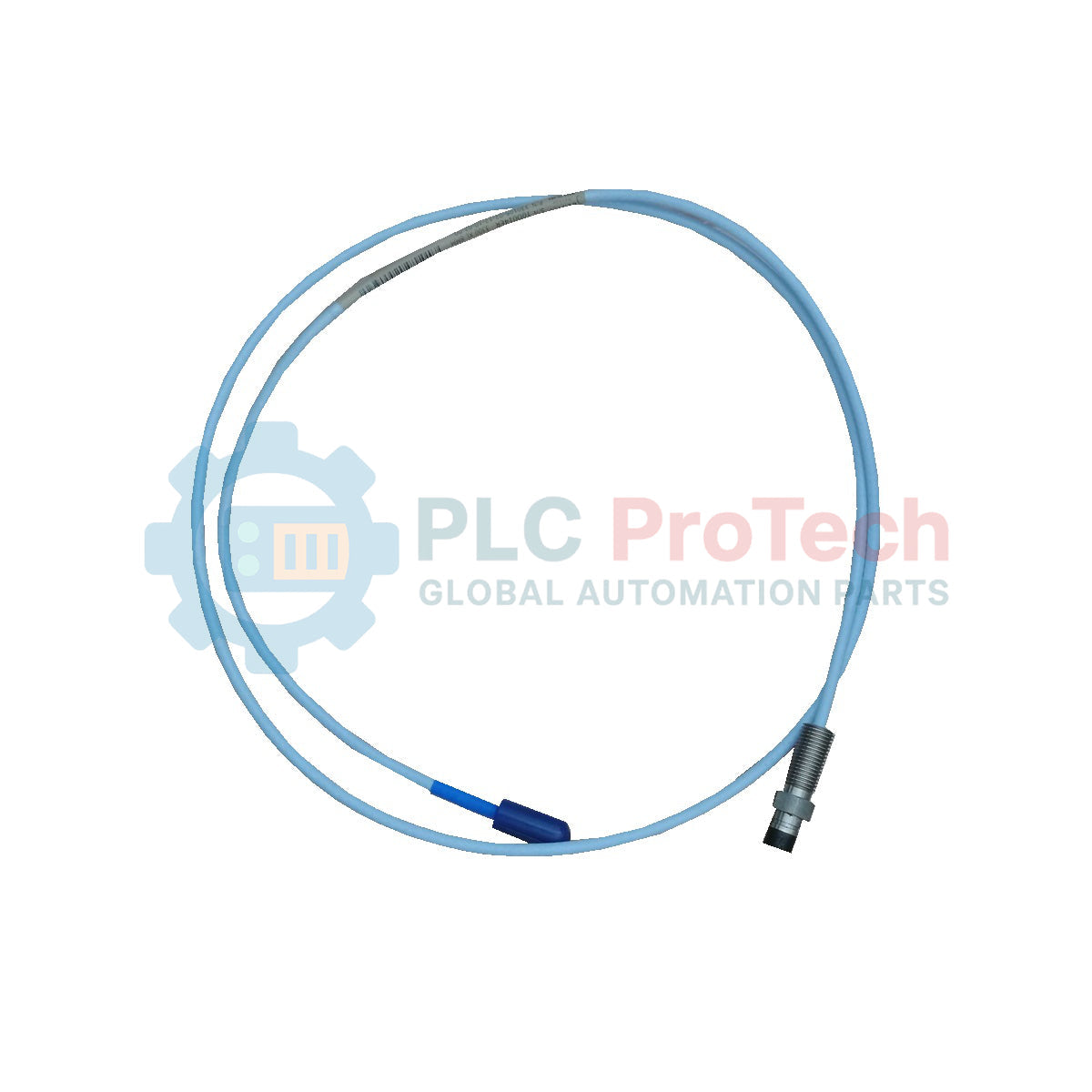
Description
Optimized for demanding rotating machinery monitoring, the Bently Nevada 330105-02-12-10-12-CN eddy current proximity probe delivers highly reliable, non-contact measurements of shaft vibration, axial position, and oil-film dynamic behavior. As an integral component of the 3300 XL 8 mm Transducer System, this reverse-mount probe features a 3/8-24 UNF threaded case, physical fluid sealing, and robust physical construction to withstand continuous exposure to extreme industrial environments. It translates physical gap changes into proportional voltage signals when coupled with a calibrated 3300 XL Proximitor Sensor, allowing plant operators to identify machinery instability before failure occurs.
Features
-
FluidLoc Cable Technology: Prevents process fluids, lubricating oils, and moisture from migrating through the internal jacket of the coaxial cable.
-
High-Performance Tip Material: Built with Polyphenylene sulfide (PPS) to resist chemical degradation, erosion, and high-temperature oxidation.
-
ClickLoc Coaxial Connection: Gold-plated miniature connector offers a secure, vibration-resistant connection with low contact resistance.
-
Rugged Housing Design: Crafted from AISI 303 or AISI 304 stainless steel to maintain structural integrity under high-pressure conditions.
-
System Compatibility: Fully interchangeable with existing 3300 XL series 8 mm extension cables and proximity sensor electronics.
Applications
- Steam turbine and gas turbine shaft vibration analysis.
- Radial thrust and dynamic axial displacement profiling in centrifugal compressors.
- Critical gearbox shaft misalignment and eccentricity monitoring.
- Hydroelectric generator thrust collar and bearing clearance tracking.
- High-speed industrial pump and fan shaft motion diagnostics.
Technical Specifications
| Parameter |
Specification Value |
| Manufacturer |
Bently Nevada |
| Model Number |
330105-02-12-10-12-CN |
| Transducer Series |
3300 XL 8 mm |
| Mounting Configuration |
Reverse Mount |
| Unthreaded Case Length (02) |
0.2 inches (5.1 mm) |
| Overall Case Length (12) |
1.2 inches (30.5 mm) |
| Total Length Option (10) |
1.0 meter (3.3 feet) |
| Thread Size |
3/8-24 UNF |
| Connector Option (12) |
Miniature ClickLoc coaxial connector, FluidLoc cable |
| Agency Approval (CN) |
Country-specific approvals (China/Ex) |
| Probe Tip Material |
Polyphenylene sulfide (PPS) |
| Probe Case Material |
AISI 303 or 304 stainless steel (SST) |
| Operating Temperature Range |
-51 degC to +177 degC (-60 degF to +350 degF) |
| Country of Origin |
United States (U.S.A.) |
| Shipping Weight (Calculated) |
2.0 kg (4.4 lbs) |
Connections and Interfaces
| Connection Interface |
Function / Assignment |
| Coaxial Center Conductor |
Carries high-frequency radio frequency (RF) signal to drive eddy current field. |
| Coaxial Outer Shield |
Common system return line and electrical noise barrier. |
| Miniature ClickLoc Plug |
Direct quick-connect coupling to the 3300 XL extension cable socket interface. |
Empirical Engineering Insights
Alternative Models & Compatibility
This 1.0-meter probe requires matching extension cables and Proximitor electronics calibrated specifically for an overall 5.0-meter or 9.0-meter physical system length. Standardizing on the 3300 XL 8 mm system provides backwards compatibility with older 3300 series 5 mm and 8 mm components; however, using mixed legacy configurations will alter the output scale factor from the typical 7.87 V/mm (200 mV/mil). Ensure the model thread type (3/8-24 UNF) matches the machine casing tap geometry before attempting installation.
Application Pitfalls & Engineering Notes
Reverse-mount configurations are physically installed from the outside of the machine casing or inside a dedicated sleeve. A common point of commissioning failure is over-tightening of the probe thread, which can deform the internal sensor housing or damage the PPS tip. In high-temperature casing environments, differential thermal expansion between the stainless steel probe case and the carbon steel machine housing must be calculated to prevent the physical gap from dropping to zero during thermal transients.
Commissioning & Wiring Tips
Always maintain minimum clearance around the probe tip to prevent side-viewing effects, which distort the output voltage calibration. The coaxial cable routing must avoid sharp bends; the minimum bend radius of 25.4 mm (1.0 inch) must be strictly maintained. When joining the ClickLoc connectors, ensure no solvent, oil, or physical debris enters the connection face. Apply silicone tape or a dedicated connector protector kit to shield the coaxial junction from local environmental humidity.
Installation Guidelines
CRITICAL WARNING: De-energize all machinery and isolate local field monitoring systems prior to installation. Verify that no explosive gas or dust concentrations are present in the work area when exposing electrical connections. Secure and shield all routed coaxial cabling to prevent mechanical shear or electromagnetic interference from high-voltage motor power leads.
1
Carefully thread the reverse mount probe body into the installation sleeve or casing tap by hand to ensure no cross-threading occurs.
2
Using a calibrated digital voltmeter connected to the associated Proximitor output, adjust the mechanical position of the probe until the target DC gap voltage registers within the specified linear operating range (typically -9.0 VDC to -10.0 VDC for mid-scale calibration).
3
Tighten the thread locknut to the recommended torque specifications (do not exceed 13.5 Nm or 120 in-lb) to secure the mechanical position.
4
Connect the coaxial ClickLoc plug to the corresponding extension cable and apply protective heat-shrink tubing or connector sleeves to lock out moisture.